

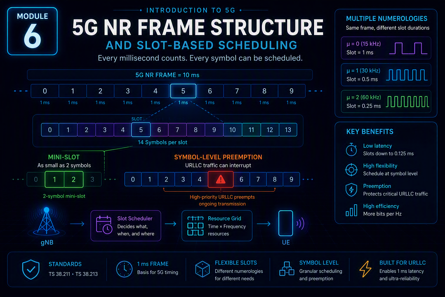
5G NR slot scheduling is defined across 3GPP TS 38.211 and TS 38.213, and it’s the layer where Module 1’s 1ms URLLC latency target actually gets implemented in concrete scheduling mechanics — mini-slots, symbol-level flexibility, and a formally defined preemption procedure that LTE’s rigid subframe model had no equivalent for.
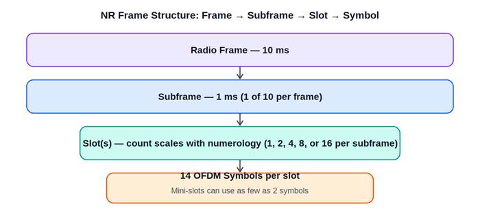
Diagram for Module 6
Diagram: 5G NR slot scheduling — frame, subframe, slot, and symbol hierarchy.
The basic frame hierarchy
A radio frame is 10ms, divided into ten subframes of 1ms each — identical to LTE at this level, per TS 38.211 Section 4.3.1. Below the subframe, the number of slots scales directly with numerology (Module 4): 1 slot at μ=0, up to 64 slots per subframe at μ=6 (Release 17). Each slot normally contains 14 OFDM symbols (7 for the rarely-used extended-CP configuration at μ=2).
Flexible slot content: symbol-level direction assignment
Unlike LTE’s largely fixed subframe structure, each OFDM symbol within an NR slot can be independently designated downlink (D), uplink (U), or flexible (F), via a combination of semi-static RRC configuration (TDD-UL-DL-ConfigCommon, per TS 38.331) and dynamic Layer 1 signaling. This symbol-level granularity is genuinely new relative to LTE and is one of the concrete mechanisms enabling NR’s latency performance.
Mini-slots: the mechanism that actually delivers low latency
The single most important scheduling innovation for URLLC is the mini-slot, formally supporting PDSCH/PUSCH mappings as short as 2, 4, or 7 symbols (TS 38.214, Section 5.1.2.1), rather than requiring a full 14-symbol slot transmission. Without mini-slots, a URLLC packet arriving mid-slot would wait for the next slot boundary before transmission could begin — adding latency that stacks against URLLC’s already tight 1ms budget from Module 1. Mini-slot scheduling lets the network begin transmission almost immediately.
Preemption: DCI Format 2_1 and interrupting eMBB traffic
Even with mini-slots, a latency-critical transmission might arrive while a lower-priority eMBB transmission is already mid-flight on the same resources. NR defines an explicit preemption mechanism using DCI Format 2_1 (TS 38.212, Section 7.3.1.3), a downlink control information format specifically carrying an Interrupted Transmission Indication (INT-RNTI). When URLLC traffic preempts an eMBB transmission, the network signals via DCI 2_1 which time-frequency resources were preempted, so the affected eMBB device knows to treat that portion as unreliable and can request retransmission accordingly, rather than silently receiving corrupted data. This is a direct, standardized implementation of the eMBB/URLLC resource competition inherent to Module 1’s design brief.
Scheduling timing: K0, K1, and K2
NR’s scheduling grant explicitly signals timing offsets rather than assuming fixed timing the way LTE largely did: K0 (offset between the DL grant in PDCCH and the actual PDSCH data), K1 (offset between PDSCH reception and the HARQ ACK/NACK on PUCCH), and K2 (offset between an uplink grant and the actual PUSCH transmission) — each independently configurable per numerology, per TS 38.214. This explicit signaling is itself part of what makes flexible mini-slot and preemption scheduling possible: the network isn’t locked into LTE’s largely implicit, fixed 4ms-class timing relationships.
Why LTE’s scheduling model couldn’t simply be reused
LTE’s subframe-based scheduling, built around a fixed 1ms transmission time interval, was well matched to LTE’s broadband-first design goal but structurally couldn’t deliver URLLC-class latency no matter how it was tuned — the minimum granularity of a full 1ms subframe was itself larger than URLLC’s entire 1ms latency budget in many target use cases. NR needed genuinely new mechanisms, not incremental tuning of LTE’s existing ones.
The practical takeaway
NR’s frame structure — flexible slot counts per numerology, per-symbol direction flexibility, mini-slots, DCI 2_1 preemption, and explicit K0/K1/K2 timing — is where 5G’s latency ambitions actually get implemented at the radio-resource level. It’s considerably more intricate than LTE’s comparatively rigid subframe model, and that complexity is a direct, necessary consequence of serving eMBB and URLLC traffic well on the same radio interface.
Next in this series: Module 7 — Massive MIMO and Beamforming: How 5G Gets More Capacity From the Same Spectrum.