

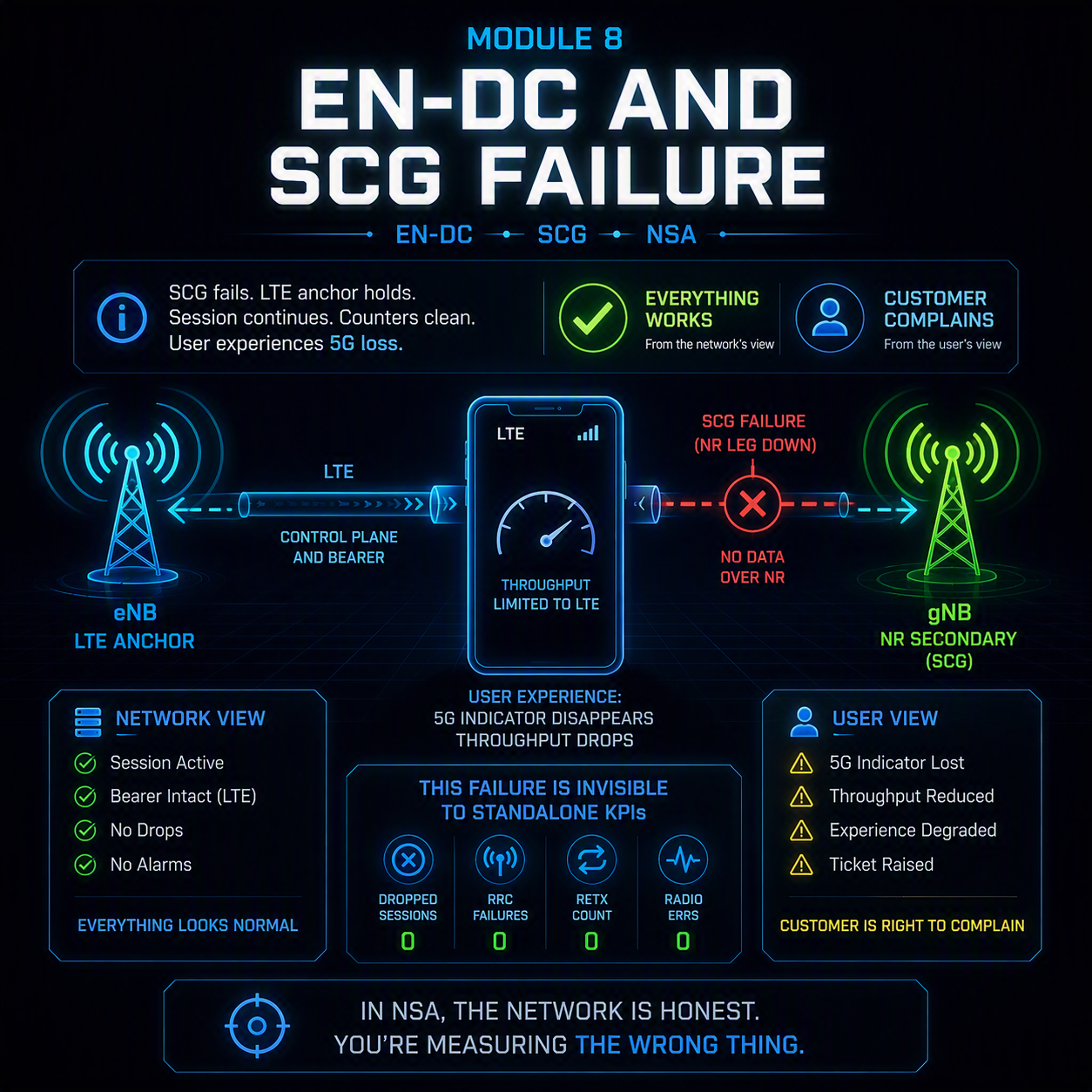
An EN-DC SCG failure is the only fault in this course where everything works and the customer is still right to complain. The NR leg fails, the LTE anchor holds the session, the data keeps flowing at LTE speed, and not a single drop counter moves. The user sees the 5G indicator disappear and reports a drop. The network sees nothing at all.
That asymmetry is the whole module. In non-standalone deployments the mobile network is honestly reporting that no session was lost, while the thing the operator actually sold — 5G throughput — was lost repeatedly. If you are measuring an NSA network with standalone KPIs, this failure class is invisible by construction.
Nothing dropped. The customer still lost their 5G, and your drop rate will never tell you how often.
In this module
- Part 1 — EN-DC architecture: what fails and what survives
- Part 2 — SgNB addition: where the 5G leg is won or lost
- Part 3 — The EN-DC SCG failure procedure, step by step
- Part 4 — The six failure types and what each one means
- Part 5 — The uplink imbalance, and why B1 is the master control
- Part 6 — PSCell change: mobility on the secondary leg
- Part 7 — Bearer options and where traffic actually goes
- Part 8 — Device capability and band combination faults
- Part 9 — The KPIs that hide EN-DC SCG failure
- Part 10 — Worked example
- Part 11 — The full decision tree
Part 1 — EN-DC architecture: what fails and what survives
In EN-DC the UE has two radio legs and one control anchor. The LTE eNB is the master node: it owns the RRC connection, the signaling radio bearers and the connection to the EPC. The NR en-gNB is the secondary node, carrying a secondary cell group — the SCG — that exists to add throughput.
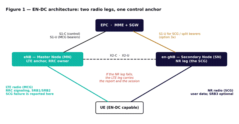
Figure 1 — EN-DC architecture. The LTE leg owns control, so it survives an NR failure and carries the report about it.
Three consequences follow from that structure, and they explain nearly every diagnostic oddity in this module.
- The NR leg is optional. Losing it degrades throughput; it does not end the session. There is no drop to count.
- Failure is reported over LTE. The UE tells the master node about the NR failure using the LTE connection, which is still working. This is why recovery is orderly and why the event never touches NR access counters.
- The master node decides what happens next. The NR node does not get a say in its own release. Configuration on the LTE side therefore governs NR retention, which is not where engineers look first.
The core is the EPC, not the 5G core, so none of the 5G core procedures apply. If the LTE attach side is unfamiliar, the basic LTE call flow covers it, and detach cause analysis in LTE covers the cases where the anchor itself fails — which ends the session for real.
Part 2 — SgNB addition: where the 5G leg is won or lost
Before anything can fail, the NR leg has to be added. The UE attaches on LTE, the eNB configures a B1 measurement for NR, and when the UE reports an NR cell above the B1 threshold the eNB asks the en-gNB to add the SCG.
Most EN-DC problems that reach a customer are really addition problems rather than failure problems: the 5G leg is added late, added and immediately lost, or never added at all. Three things decide it.
| Decision point | What governs it | What goes wrong |
| Is NR measured at all | B1 measurement configuration on the eNB | UE never configured to measure the NR frequency |
| Is the reported cell good enough | The B1 threshold | Threshold set on downlink reach alone — see Part 5 |
| Can the SgNB admit the UE | Admission control, capability check, X2 | Band combination unsupported, or X2 unavailable |
Track addition success and addition attempts separately from failure counts. A cell where SgNB addition is rarely attempted has an LTE-side measurement configuration problem, and it will look perfectly healthy on every NR KPI precisely because almost nothing is using NR.
Part 3 — The EN-DC SCG failure procedure, step by step
When the NR leg does fail, the procedure is orderly, and knowing it tells you which node holds the evidence.
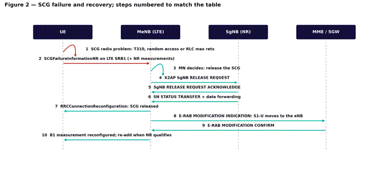
Figure 2 — SCG failure and recovery. Step numbers match the table below. The session never stops.
| Step | What happens | What it gives you |
| 1 | The UE detects an NR radio problem | The failure type — this is the field that matters most |
| 2 | UE sends SCGFailureInformationNR on the LTE connection | The report, plus NR measurements at the moment of failure |
| 3 | Master node decides to release the SCG | LTE-side configuration governs this, not NR |
| 4–5 | X2 SgNB release request and acknowledgement | X2 faults show up here, not as radio failures |
| 6 | Status transfer and data forwarding | Prevents a data gap during the transition |
| 7 | UE is reconfigured with the SCG released | The moment the 5G indicator disappears for the user |
| 8–9 | Bearer path moves back to the eNB | Traffic continues at LTE speed |
| 10 | B1 measurement reconfigured for re-addition | How quickly 5G returns depends on this |
Step 2 is the whole diagnostic. The SCGFailureInformationNR message carries both the failure type and the UE’s NR measurements at the instant of failure, which together separate a coverage problem from an uplink problem from a configuration problem without any further investigation. It is the EN-DC equivalent of the RLF report covered in Module 3, and like the RLF report it is routinely discarded rather than collected.
If you are not collecting SCG failure reports, you are diagnosing this fault class with no evidence at all.
Part 4 — The six failure types and what each one means
The failure type field takes one of six values, and each points somewhere different.
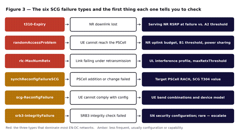
Figure 3 — The six SCG failure types and the first thing each one tells you to check.
The three that dominate
t310-Expiry means the NR downlink degraded past recovery — the same timer mechanics as standalone RLF, covered in radio link failure in LTE and applying identically to NR. It is a genuine coverage finding: the PSCell was too weak. Check the NR serving RSRP recorded in the report against the A2 release threshold. If the UE was held well below the point where the link was usable, the A2 threshold is set too low.
randomAccessProblem means the UE could not reach the PSCell. This is an uplink finding, not a coverage one, and it is the single most misdiagnosed EN-DC SCG failure. Part 5 covers the mechanism. The preamble side is covered in RACH preamble planning and the access procedure in NR initial access — cell search, SSB and random access.
rlc-MaxNumRetx means the link kept failing under retransmission until the limit was reached. This usually points at uplink interference or at link adaptation that is over-optimistic for the conditions. HARQ explains why the retransmission layers absorb loss up to a point and what happens past it.
The three that are usually configuration
- synchReconfigFailureSCG — the UE failed to synchronize to a PSCell it was told to move to. Covered in Part 6.
- scg-ReconfigFailure — the UE could not apply the configuration it was given. Covered in Part 8; this is almost always a capability or band combination mismatch.
- srb3-IntegrityFailure — an integrity check failed on the direct signaling bearer to the NR node. Rare, and a security configuration issue rather than a radio one. Escalate rather than tune.
Triage rule: split SCG failures by type before doing anything else. The three dominant types lead to three different teams — coverage, uplink and interference — and a blended SCG failure rate points at none of them.
Part 5 — The uplink imbalance, and why B1 is the master control
This is the central mechanism of the module. Mid-band NR with massive MIMO produces a downlink that reaches considerably further than the uplink can answer, because array gain and beamforming apply on the transmit side and the UE has neither. The result is a ring around every NR cell where the UE can measure an excellent signal it cannot actually use.
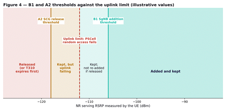
Figure 4 — B1 and A2 against the uplink limit. Illustrative values; the relationship is the point, not the numbers.
B1 is a downlink measurement. If the threshold is set where the downlink is good, UEs will be added into the amber band in Figure 4 — strong enough to report, too far to reach the cell on the uplink. Every one of those additions becomes a randomAccessProblem failure sooner or later.
The fix is counterintuitive enough that it meets resistance: raise the B1 threshold. That shrinks the reported 5G footprint slightly, and it eliminates most random access failures, because UEs are only added where they can sustain the connection. Coverage maps look marginally worse; measured 5G retention improves substantially, and so does the customer experience, because the UE stops cycling between adding and losing the NR leg.
The asymmetry itself is a design property rather than a fault. Massive MIMO and beamforming covers why array gain benefits the downlink far more than the uplink, and the CU/DU/RU split covers which part of the chain each measurement is actually reporting on.
A2 is the mirror control. Set it too low and UEs are retained on a PSCell that has stopped working, which converts what should be an orderly release into a t310-Expiry failure and a period of degraded service before it. Set it too high and UEs are released from cells that were still usable, which produces unnecessary churn. The two thresholds should be tuned together, with the gap between them wide enough to avoid oscillation.
B1 is a downlink threshold controlling a decision the uplink has to live with. That single mismatch causes most EN-DC SCG failures.
Part 6 — PSCell change: mobility on the secondary leg
The NR leg has its own mobility. When a better PSCell becomes available, the UE is moved to it — and the procedure has its own T304 and its own failure signature.
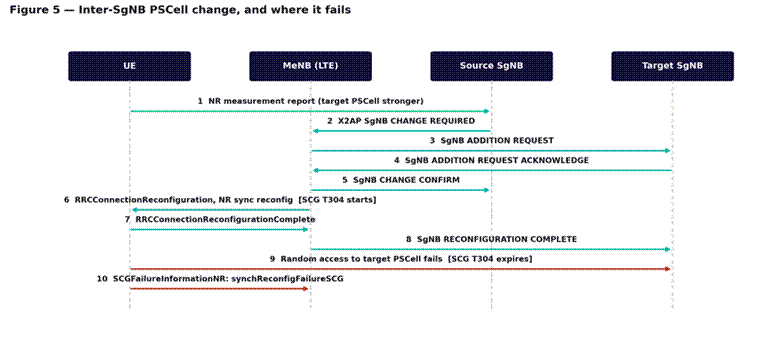
Figure 5 — Inter-SgNB PSCell change. Failure at step 9 produces synchReconfigFailureSCG, not a handover failure.
Two things make PSCell change failures easy to miss. First, they are not handover failures and do not appear in handover KPIs — Module 7’s counters will not show them. Second, a failed PSCell change ends in SCG release, so the symptom is again a disappearing 5G indicator rather than anything that looks like mobility.
The most common cause is the same uplink imbalance as Part 5, applied to the target rather than the source: the UE is moved to a PSCell it can hear but cannot reach, and random access at step 9 fails. The second most common is an SCG T304 set too short for the target’s access time.
Triage: for any cluster with elevated synchReconfigFailureSCG, split by target PSCell rather than by source. A single target cell that UEs cannot access will produce failures from every source around it, and a source-based view spreads that signal thinly across many cells.
Part 7 — Bearer options and where traffic actually goes
Which bearer option is configured determines what the user loses when the SCG goes. Most deployments use option 3x, where the user plane is anchored at the NR node and split from there, but the variants behave differently under failure.
| Option | Where the user plane is anchored | What an SCG failure costs |
| 3 | At the eNB, split toward the NR leg | LTE path already exists; transition is least disruptive |
| 3a | Split at the core; separate bearers per leg | NR-carried bearers must be moved; brief interruption |
| 3x | At the en-gNB, split back toward LTE | Path must move back to the eNB — steps 8 and 9 of Figure 2 |
The practical consequence is that in option 3x an SCG failure requires a bearer path change through the EPC, so a failure rate that is tolerable on paper produces a measurable interruption in practice. If users report stalls rather than just slower speeds when 5G drops out, the bearer option and the time taken for steps 8 and 9 are worth measuring directly.
Throughput on a split bearer is also bounded by the slower leg’s contribution to reordering, which means a marginal NR leg can deliver less aggregate throughput than LTE alone. A UE oscillating between adding and releasing the SCG can therefore be measurably worse off than one that never had 5G at all — which is the strongest practical argument for raising B1 rather than chasing footprint.
Part 8 — Device capability and band combination faults
EN-DC depends on the UE supporting the specific combination of LTE and NR bands being asked of it. Support is per combination, not per band, and it varies by device model, chipset and firmware.
scg-ReconfigFailure is the signature. The UE was given a configuration it could not apply, and the finding is a capability mismatch rather than anything in the radio environment. It concentrates on particular device models, which makes it easy to identify and easy to miss: split SCG failures by device model, and a capability fault is obvious within minutes.
- One model failing everywhere is a capability or firmware fault. Check the reported band combinations against what the network is configuring.
- All models failing in one place is a radio or configuration fault. Go back to Part 5.
- One model failing in one place usually means that model is more uplink-limited than the rest, which points at Part 5 again rather than at capability.
Uplink power sharing between the LTE and NR legs is worth checking alongside this. A UE splitting its transmit power across two carriers has less available for each, which tightens the uplink limit further — and devices implement the sharing differently, which is why one model can fail at a distance where others do not.
Part 9 — The KPIs that hide EN-DC SCG failure
Standard mobile network KPIs were built for a world where losing radio meant losing the session. In EN-DC that assumption is false, and every KPI built on it reports success during a failure.
| Standard KPI | Why it misses EN-DC SCG failure | Measure this instead |
| Session drop rate | Nothing drops; the LTE leg holds the session | SCG retention: time on NR against time connected |
| Handover success rate | PSCell change is not a handover | PSCell change attempts and successes, by target |
| Accessibility | Measured on LTE, which is working | SgNB addition attempts and success rate |
| NR cell availability | The cell is up; UEs cannot use it | Random access success on NR, split from addition |
| Average throughput | Averaged over LTE-only and EN-DC periods | Throughput conditioned on SCG being present |
The most useful single number is SCG retention — the proportion of connected time a UE actually spends with the NR leg active. It is the metric that turns this entire fault class from invisible into measurable, and it is not a standard KPI on most OSS installations, so it usually has to be constructed.
Counter names differ by vendor while the measurement points do not. 3GPP TS 28.552 defines where each one increments; Huawei uses its N.<Domain>.<Metric> convention and Ericsson a pm prefix, and Nokia places the equivalents in numbered NetAct measurement classes. Confirm the exact strings against the counter reference for your own software baseline before building a report on them.
Part 10 — Worked example
A marketing team reports that customers in a newly launched district complain about 5G that keeps disappearing. Network operations finds nothing: drop rate is 0.3 percent, LTE accessibility is normal, NR cell availability is 100 percent, and average throughput has actually risen since launch. Two site visits confirm the equipment is healthy.
Building the missing metric. SCG retention is constructed from addition and release counters and comes out at 41 percent. Customers in the district are spending well under half their connected time on the NR leg, which matches the complaint exactly and appears in no standard KPI.
Splitting the failures. SCG failure reports are enabled and collected for a week. Of the failures, roughly three quarters are randomAccessProblem, about a fifth are t310-Expiry, and the remainder are spread across the other four types. That distribution is the finding: this is not a coverage problem, it is an access problem.
Reading the measurements. The NR measurements carried in the failure reports show serving RSRP at the moment of failure clustered well above the level at which coverage would be the explanation. UEs were reporting a good downlink and then failing to reach the cell — the amber band in Figure 4.
The mechanism. The district launched on mid-band NR with a B1 threshold copied from an existing low-band deployment, where downlink and uplink reach are far better matched. On mid-band that threshold sits well outside the uplink limit, so UEs across a wide ring were being added into cells they could never sustain, failing random access, being released, and being re-added as soon as the B1 condition was met again. The cycle is why average throughput rose — the periods with NR were genuinely fast — while the customer experience was of 5G flickering on and off.
The fix. Raising the B1 threshold on the mid-band layer in that district, and widening the gap to A2 to stop UEs oscillating at the boundary. SCG retention rose from 41 percent to above 80. The reported 5G coverage area shrank slightly, which took some explaining, and the complaints stopped.
What made it findable: constructing SCG retention before investigating anything. Every existing KPI said the network was healthy, and every one of them was correct about the thing it measured.
Part 11 — The full decision tree
Step 1 — Confirm the fault class
- Check whether LTE data continued through the reported outage. If it did, this is an EN-DC SCG failure and not a drop.
- Construct SCG retention if you do not already have it. Without it there is no measurement of the problem.
- Separate addition failures from retention failures. A leg that is never added is a Part 2 problem, not a Part 4 one.
Step 2 — Collect the evidence
- Confirm SCG failure reporting is enabled. If it is not, enable it and wait a week rather than guessing.
- Split failures by type before splitting by anything else.
- Split by device model as a second cut. A single model dominating points at Part 8.
Step 3 — Follow the dominant type
- randomAccessProblem dominant: go to Part 5. Check B1 against the uplink limit, and check uplink power sharing.
- t310-Expiry dominant: check A2 against where the link actually stops working. This is the genuine coverage case.
- rlc-MaxNumRetx dominant: check uplink interference and the retransmission threshold.
- synchReconfigFailureSCG dominant: go to Part 6 and split by target PSCell.
- scg-ReconfigFailure dominant: go to Part 8 and check band combinations against device capability.
Step 4 — Change B1 and A2 together, not separately
- Raising B1 reduces addition into unsustainable conditions. Expect the reported footprint to shrink.
- Set A2 so the gap to B1 is wide enough to prevent oscillation at the boundary.
- Apply to the affected layer and district, not network-wide. Low-band and mid-band need different values.
Step 5 — Judge against retention, not coverage
- Re-measure SCG retention over at least a full day.
- Confirm against the original complaint. A footprint that shrank while retention rose is the intended outcome, and it needs explaining to whoever owns the coverage map.
- Check that throughput conditioned on SCG presence did not fall — if it did, the threshold moved too far.
What comes next
This completes the course as currently planned: fault classes A through D, across radio, transport and core, in both standalone and non-standalone deployments. The full set is indexed on the 5G Troubleshooting Guide. If you need the underlying architecture, the 14-module Introduction to 5G course covers the air interface and core design this course assumes.