

Originally published on 4GNation, March 2016 — republished here as part of the Telco & Beyond Engineering Archive.
This is one of the more detailed pieces I wrote during my RF engineering days, walking through everything an LTE terminal has to do before it can send or receive a single byte of data — from the first synchronization signal to a fully established RRC connection. I’ve kept the original Q&A format I used at the time, since it mirrors how I actually worked through the problem as a young engineer: not just memorizing the steps, but repeatedly asking “why does the UE know to do this next?” That habit of questioning the mechanism rather than just the sequence is, looking back, the same instinct that later made me effective translating network engineering into commercial and business conversations.
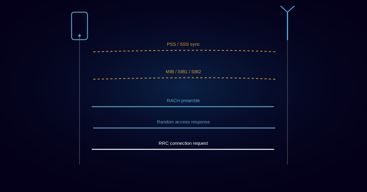
An LTE terminal must perform certain steps before it can receive or transmit data. These steps can be categorized into cell search and cell selection, derivation of system information, and random access. The complete procedure is known as LTE Initial Access.
Successful execution of the cell search and selection procedure, as well as acquiring initial system information, is essential for the UE before it can take further steps to communicate with the network. For this reason, it’s worth taking a closer look at this fundamental physical layer procedure.
My advice at the time — and it still holds — was to keep the big picture in view. Whenever you hit an issue or a new concept, ask yourself: “Where does this sit in the whole process?”
Step A: Initial Synchronization
Step A-1: Primary Synchronization Signal
The UE first looks for the Primary Synchronization Signal (PSS), transmitted in the last OFDM symbol of the first time slot of the first subframe (subframe 0) in a radio frame. This lets the UE acquire slot boundary independent of the cyclic prefix chosen for that cell. Based on the downlink frame structure (Type 1, FDD), the PSS is transmitted twice per radio frame — repeated in subframe 5 (time slot 11) — enabling the UE to time-synchronize on a 5ms basis, which simplifies the inter-frequency and inter-RAT measurements required later.
How does the UE know where to look for PSS? It doesn’t need much guesswork — synchronization signals are always sent on the center 62 subcarriers, regardless of channel bandwidth (1.25, 3, 5, 10, 20 MHz). So the UE checks the central subcarriers at the last OFDM symbol of the 1st time slot, and again at the last OFDM symbol of the 11th slot. That gets it synchronized at the slot level.
Step A-2: Secondary Synchronization Signal
Once the UE has found the 5ms timing, the next step is obtaining radio frame timing and the cell’s group identity — found via the SSS. In the time domain, SSS is transmitted in the symbol immediately before PSS, with the same 5ms periodicity (subframes 0 and 5).
How does the UE know where to look for SSS? Once PSS is identified, SSS is always sent in the slot immediately preceding it.
From these two signals, the UE derives the Cell ID:
- From PSS: Physical Layer Cell Identity (values 0, 1, 2)
- From SSS: Physical Layer Cell Identity Group (values 0–167)
Formula: Cell ID = (3 × Physical Layer Cell Identity Group) + Physical Layer Cell Identity
Step A-3: Downlink Reference Signal
The UE becomes fully synchronized because reference signals are transmitted in well-defined resource elements — every sixth subcarrier in frequency, every fourth OFDM symbol in time. Each resource block carries four reference symbols.
Step B: Broadcast of Essential System Information
Step B-4: Master Information Block (MIB)
From the MIB, the UE gets: channel bandwidth (in Resource Blocks), the System Frame Number (SFN), and PHICH configuration (used for HARQ ACK/NACK).
How does the UE read the MIB? It’s transmitted on the physical channel BCCH-BCH-PBCH, always occupying the central 72 subcarriers regardless of bandwidth. First transmission is scheduled in subframe 0 of radio frames where SFN mod 4 = 0, with repetitions in subframe 0 of all other radio frames.
Step B-5: SIB1
- Cell Access Related Information — PLMN Identity List, PLMN Identity, TA Code, Cell Identity & Cell Status
- Cell Selection Information — Minimum Receiver Level
- Scheduling Information — SI message type & periodicity, SIB mapping info, SI window length
Step B-6: SIB2
- Access Barring Information — Access Probability Factor, Access Class Barring List, Access Class Barring Time
- Semi-static Common Channel Configuration — Random Access Parameters, PRACH Configuration
- UL Frequency Information — UL EARFCN, UL Bandwidth, additional emission info
After this, the UE is downlink-synchronized and has read SIB1 and SIB2 — but it still needs uplink synchronization before it can use network services. That’s where the Random Access Procedure (RAP) comes in.
Random Access Procedure
There are two types:
- Contention-Based RAP
- Non-Contention-Based RAP
Typical Contention-Based RACH Procedure:
- UE → NW: RACH Preamble (RA-RNTI, indication for L2/L3 message size)
- UE ← NW: Random Access Response (Timing Advance, T-C-RNTI, UL grant for L2/L3 message)
- UE → NW: L2/L3 message
- Message for early contention resolution
Typical Contention-Free RACH Procedure:
- UE ← NW: RACH Preamble Assignment
- UE → NW: RACH Preamble (RA-RNTI, indication for L2/L3 message size)
- UE ← NW: Random Access Response (Timing Advance, C-RNTI, UL grant for L2/L3 message)
Contention-Based RAP in Detail
Multiple UEs can attempt to connect at the same time. The eNB has to intelligently handle this, since every UE needs to become unique to the network.
If UEs send the same Preamble ID, collisions — “contention” — occur, and the network runs a “Contention Resolution” step to sort it out.
Step 1: The UE indicates its resource requirement to the network (Preamble ID, RA-RNTI).
How does the UE select these parameters? Most of this comes via SIB2:
- The UE MAC layer selects the Preamble sequence (Group A or Group B)
- It configures the max retries it will attempt if it doesn’t receive a Random Access Response (RAR)
- It determines how much to increase power after every retry
- The MAC layer builds the RAP message and passes it to the PHY layer, which transmits it on PRACH
- After transmitting on PRACH, the UE starts looking for RAR after 3 subframes — a number fixed by 3GPP
How long should the UE keep monitoring for RAR? After those 3 subframes, the UE watches for RAR within the “window length” specified in SIB2. If it doesn’t arrive in time, the UE goes back to transmitting RAP.
Step 2: The eNB conveys reserved resources along with Timing Advance (TA), Preamble ID, and T-CRNTI (generated by the eNB), asking the UE to send an RRC connection.
Step 3: The UE sends the RRC Connection Request using the resources given by the eNB, along with an identifier (CRI) used later for contention resolution.
Step 4: The eNB generates a C-RNTI — a permanent ID for the UE for the life of the connection — and sends it to the UE. Only the UE that receives this ID proceeds; the others back off and retry.
When Multiple UEs Collide
- Multiple UEs initiate RACH with the same Preamble sequence and RA-RNTI.
- They all receive the same T-C-RNTI and resource allocation.
- All UEs send msg3 (RRC Connection Request) through the same allocated resource.
- Two timers start: T300 (RRC Connection Request transmission) and the Contention Resolution Timer (from SIB2). If msg4 (Contention Resolution) isn’t received before this timer expires, the UE returns to Step 1.
How should the eNB behave in this scenario?
- Interference case: the signals interfere with each other and the eNB decodes neither — no UE gets a HARQ ACK, and all go back to Step 1.
- Partial success: the eNB decodes only one UE’s message successfully; that UE gets a HARQ ACK.
- Full collision decoded: the eNB receives msg3 from both UEs and sends msg4 (Contention Resolution) with a MAC CRI to both. Each UE’s MAC layer compares the received CRI against its own — the one that matches proceeds to decode RRC Connection Setup; the other backs off and restarts RA.
Contention Resolution comes in two flavors:
MAC-based:
- Uses C-RNTI on PDCCH
- Uses the DCCH logical channel
- Used in handover scenarios
- Rule: if the UE has a valid C-RNTI going into RA, it’s MAC-based
L1-based:
- Uses CRI (Contention Resolution Identity) on DL-SCH
- Addressed to T-CRNTI
- Uses the CCCH logical channel
- Rule: if the UE has no valid C-RNTI going into RA, it’s L1-based
Exactly when and where does a UE transmit RACH? Refer to 3GPP TS36.211, Table 5.7.1-2 — it specifies, per “PRACH Configuration Index,” exactly which SFN and subframe the UE is allowed to transmit on. For example, PRACH Configuration Index 0 only allows RACH transmission in even-numbered SFNs, specifically at subframe number 1.
How does the network know when the UE will transmit RACH? Simply — the network tells the UE in advance when to transmit. If the UE fails to correctly decode that configuration, the network won’t be listening at the right moment even if the UE does send RACH.
Exactly when does the network transmit the RACH Response? Per 3GPP 36.321 (Section 5.1.4): once the preamble is transmitted, the UE monitors PDCCH for the Random Access Response, starting at the subframe containing the end of preamble transmission plus 3 subframes, for a length defined by ra-ResponseWindowSize. So the earliest possible response is 3 subframes after preamble end, and the window itself can run 0–10 subframes — meaning the maximum gap between preamble and response is a tight 12ms.
When should the UE send the next PRACH if it doesn’t get a response? The Backoff Indicator (BI) answers this — a MAC subheader specifying the delay before the next PRACH attempt. A BI field value of 10, for example, maps to a 320ms backoff parameter, meaning the UE can retry any time in that 0–320ms window. BI is a 4-bit field (values 0–15), always positioned at the start of the MAC header when present — and it’s optional, sent only when the network situation calls for it. Notably, BI carries no payload of its own; it’s fully contained in the header/subheader.
Reference: lteexpert.blogspot.com