

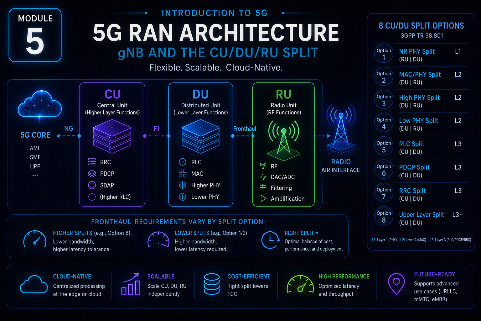
The 5G CU DU RU split isn’t a single fixed architecture — 3GPP TR 38.801 defines eight distinct functional split options between these components, each cutting the radio protocol stack at a different point, with genuinely different fronthaul bandwidth and latency requirements. Understanding which split option a deployment uses matters enormously for real network planning, not just conceptual understanding.
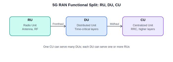
Diagram for Module 5
Diagram: The 5G CU DU RU split — RU, DU, and CU functional division.
The gNB, and why a single-box model starts to strain
The gNB is 5G’s equivalent of LTE’s eNodeB. It can be deployed as a single integrated unit, but 5G’s higher-frequency deployments (FR2/mmWave, Module 2) and push toward much denser small-cell deployments created a practical problem: deploying full-featured, self-contained base stations at every dense small-cell site is expensive and operationally complex at 5G’s expected density.
The eight functional split options, per 3GPP TR 38.801
| Option | Split point | Data rate impact | Latency requirement | Typical use |
| Option 1 | RRC / PDCP | Low fronthaul demand | Relaxed | Rarely used alone |
| Option 2 | PDCP / RLC (high) | Moderate | Relaxed (~ms) | Common CU/DU split point |
| Option 3 | Intra-RLC | Moderate | Relaxed | Less common |
| Option 4 | RLC / MAC | Moderate–high | Tighter | Less common |
| Option 5 | Intra-MAC | High | Tight | Rare |
| Option 6 | MAC / PHY | High | Tight (~ms) | Some vendor implementations |
| Option 7 (7.1, 7.2, 7.3) | Intra-PHY | Very high (7.2: ~10 Gbps class) | Very tight (7.2: <100 µs class) | Most common O-RAN DU/RU split (7.2x) |
| Option 8 | PHY / RF | Highest | Extremely tight | Traditional integrated RRH/BBU split |
Source: 3GPP TR 38.801, Section 5.2 (Functional split options for NR).
The industry’s overwhelming practical convergence — driven substantially by the O-RAN Alliance — has been on Option 2 for the CU/DU split and a variant of Option 7.2 for the DU/RU split, because 7.2x delivers a workable middle ground: it moves enough real-time physical-layer processing (like beamforming weight application) to the RU to keep fronthaul bandwidth manageable, while still centralizing enough of the PHY layer at the DU to allow meaningful multi-cell coordination.
The three-way split, mapped to the option framework
- RU (Radio Unit) — sits below the Option 7.2 split point: RF, and low-level PHY functions like FFT/iFFT and cyclic prefix handling.
- DU (Distributed Unit) — sits between the Option 7.2 point and Option 2: upper PHY, MAC, and RLC, needing tight timing but not requiring co-location with the RU.
- CU (Centralized Unit) — sits above Option 2: RRC and PDCP, tolerant enough of latency to be centralized, serving multiple DUs from one location.
Why fronthaul requirements vary so drastically by split choice
This is where the option table becomes operationally critical rather than academic. An Option 8 split (the traditional BBU/RRH model) requires fronthaul capable of carrying raw, uncompressed IQ samples — bandwidth requirements scaling directly with antenna count and can reach tens of Gbps for a massive MIMO array, with latency budgets in the single-digit microseconds. An Option 7.2 split, by contrast, moves enough processing into the RU that fronthaul bandwidth drops substantially (though still commonly in the multi-Gbps range for a high-order massive MIMO configuration) while relaxing the latency budget into roughly the 100 microsecond class — a difference that directly determines whether standard fiber transport, or specialized low-latency transport, is required between RU and DU.
Why disaggregation is worth the added complexity
Centralizing the CU — and to a lesser degree the DU — across many cell sites delivers coordinated radio resource management across cells far more effectively than fully independent base stations, directly useful for the coordination that dense small-cell deployments and massive MIMO (Module 7) benefit from; simpler, cheaper cell-site hardware at the RU/DU level, since less processing needs to be pushed to potentially thousands of dense small-cell locations; and faster feature deployment, since software updates at a centralized CU roll out across every DU it serves at once.
What comes next
This disaggregation is the RAN-side expression of an architectural instinct that reappears in 5G Core (starting Module 9): breaking previously monolithic network elements into smaller, more flexible, independently deployable components — trading a simpler, more rigid single-box design for one that’s more complex but considerably more scalable.
Next in this series: Module 6 — 5G NR Frame Structure and Slot-Based Scheduling.
One thought on “Introduction to 5G — Module 5: 5G RAN Architecture — gNB and the CU/DU/RU Split Explained”