

Originally published on 4GNation, December 2015 — republished here as part of the Telco & Beyond Engineering Archive.
This is one of the simplest concepts in LTE, but also one of the most foundational — nothing in the network works without the transmitter and receiver agreeing on a shared sense of time. I used a wristwatch analogy back in 2015 to explain it to colleagues, and it still holds up as the easiest mental model for anyone new to the topic. This republished version keeps that analogy but goes considerably deeper — into how the clock is actually built, how a UE finds it cold with no prior information, and why getting this wrong breaks almost everything downstream.
Why synchronization is non-negotiable
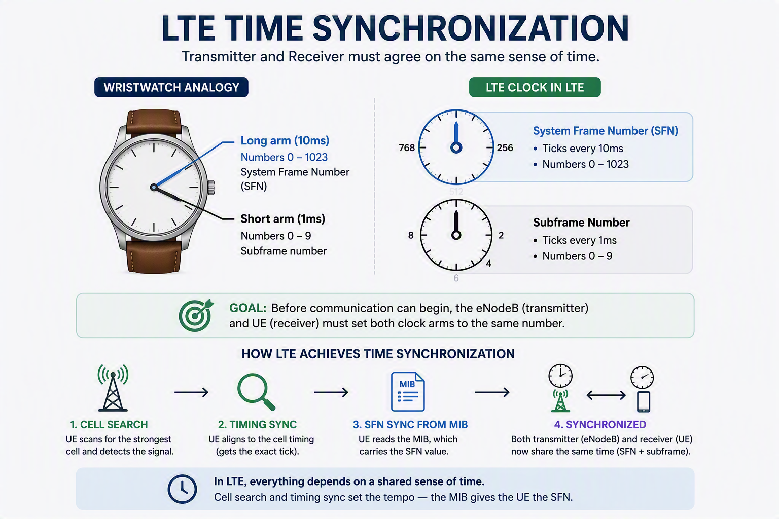
In any communication system, one of the most important requirements is that the transmitter and receiver operate at the same tempo — technically speaking, in synchronized mode. Put simply: the transmitter and receiver each have their own clock, and they need to synchronize those clocks before communication can begin.
This isn’t a nice-to-have. Every scheduling decision, every HARQ retransmission, every paging occasion, and every measurement gap in LTE is defined relative to a specific point in time. If the eNodeB and the UE don’t agree on what that point in time is, the UE will decode the wrong subframe, miss its paging occasion, or apply the wrong HARQ process — the air interface effectively stops working, even if signal strength is excellent.
The LTE clock: two hands, like a wristwatch
Like an analog wristwatch, the LTE clock has two “arms.” One ticks every 10ms, the other every 1ms. And just like a wristwatch, each arm’s ticks are numbered within a fixed range.
- The arm ticking every 10ms has numbers between 0 and 1023 — this is the System Frame Number (SFN).
- The arm ticking every 1ms has numbers between 0 and 9 — this is the subframe number.
Before the transmitter (eNodeB) and receiver (UE) can start communicating, they have to set both clock arms to the same number. This synchronization happens during cell search and timing sync. In short, they synchronize tempo — the exact moment each arm ticks — through cell search and timing sync, and the UE gets its SFN sync from the MIB, which carries the SFN value directly.
What’s actually inside a radio frame
To make the wristwatch analogy concrete, it helps to see the structure it’s describing:
| Unit | Duration | Count per parent unit | Range |
|---|---|---|---|
| Radio frame | 10 ms | — | SFN: 0–1023 |
| Subframe | 1 ms | 10 per radio frame | 0–9 |
| Slot | 0.5 ms | 2 per subframe | 0–1 |
| OFDM symbol | ~66.7 µs (normal CP) | 7 per slot (normal CP), 6 (extended CP) | — |
One full sweep of the SFN — from 0 back to 0 — takes 1024 × 10ms = 10.24 seconds. That wraparound number matters more than it looks like it should, because a lot of higher-layer procedures are defined as “every N frames, calculated from SFN,” and those calculations have to account for the wrap.
How does the UE actually find this clock with zero prior information?
This is the part the original 2015 post skipped, and it’s the part that actually separates “knowing the definition” from “understanding the system.” A UE powering on in a new cell has no idea what time it is on the network’s clock. It finds out in stages, during cell search:
Step 1 — PSS (Primary Synchronization Signal). Transmitted in the last OFDM symbol of slot 0 and slot 10 of every radio frame (subframes 0 and 5 for FDD). The PSS gives the UE slot and subframe timing — where the 1ms boundaries are — and partial physical cell identity information (1 of 3 possible sector IDs).
Step 2 — SSS (Secondary Synchronization Signal). Transmitted immediately before the PSS in the same subframes. The SSS is where frame boundary timing comes from — critically, it also tells the UE whether it’s looking at subframe 0 or subframe 5, because the SSS sequence differs between the two, resolving the 5ms ambiguity that PSS alone can’t. Combined with PSS, the UE now has the full Physical Cell ID (one of 504 possible values).
At this point the UE knows where the subframe boundaries are and which of the two SSS-carrying subframes it’s looking at — but it still doesn’t know the actual SFN value. That comes next.
Step 3 — MIB via PBCH. The Master Information Block is carried on the Physical Broadcast Channel, transmitted in subframe 0 of every radio frame. The MIB explicitly carries the 8 most significant bits of the SFN. The remaining 2 least significant bits aren’t transmitted directly — they’re inferred implicitly from which of four 10ms transmissions the UE is currently decoding within the PBCH’s 40ms Transmission Time Interval (the same MIB content is repeated across 4 consecutive radio frames with different redundancy versions, and the UE identifies its position in that 40ms cycle through blind decoding).
The practical result: after successfully decoding PSS, SSS, and MIB, the UE has both clock arms — SFN and subframe number — fully synchronized to the network, with zero prior knowledge required. This entire sequence typically completes in well under a second.
Why the SFN specifically matters beyond just “knowing the time”
It would be easy to treat SFN as a housekeeping detail. In practice, it’s referenced directly by several procedures that engineers troubleshoot regularly:
- Paging. The UE’s paging occasion is calculated using a formula involving SFN modulo the paging cycle length — get the SFN wrong and a UE will listen in the wrong subframe and miss pages entirely, which looks like a coverage or reachability problem but is actually a timing problem.
- DRX (Discontinuous Reception) cycles. The On Duration timing for a UE’s sleep/wake cycle is anchored to SFN, so battery-saving behavior depends on both sides agreeing on frame numbering.
- System Information scheduling. SIBs are broadcast on a schedule defined in terms of SFN, so a UE joining mid-cycle uses the SFN to know which SIB is coming next and when.
- MBSFN subframe allocation. For broadcast/multicast services, which subframes are MBSFN versus normal is configured relative to specific SFN values.
- HARQ timing in TDD configurations. Because TDD uplink/downlink subframe allocation is asymmetric, HARQ round-trip timing calculations reference the SFN and subframe number together to determine which subframes carry retransmissions.
One layer beyond: the Hyper Frame Number (HFN)
Since the SFN wraps every 10.24 seconds, it’s too short a counter for some purposes — most notably PDCP-layer security. Ciphering and integrity protection need a counter that doesn’t repeat for the lifetime of a security context, or replay attacks become trivial. LTE solves this with the Hyper Frame Number (HFN), which increments each time the SFN wraps around. The combination of HFN + SFN + subframe number forms the COUNT value used as an input to the ciphering algorithm — effectively extending the wristwatch analogy to a calendar sitting behind the watch face, counting how many times the watch has gone all the way around.
The engineer’s takeaway
If you’re troubleshooting a UE that’s camped on a cell with good signal quality but isn’t receiving pages, isn’t getting scheduled correctly, or is failing security setup intermittently — timing synchronization is worth checking before anything more exotic. A UE with a strong RSRP but a corrupted or stale SFN reference will behave like it has a coverage problem while the actual fault is a clock the two sides never actually agreed on. The wristwatch analogy holds all the way through: two watches that are both running perfectly well, but set to different times, are just as useless to each other as two watches that have stopped.
This same synchronized timing is what makes the entire call setup sequence in Basic LTE Call Flow possible in the first place.
One thought on “LTE Keeps Time: A Deep Dive Into System Frame Number and Subframe Synchronization”