

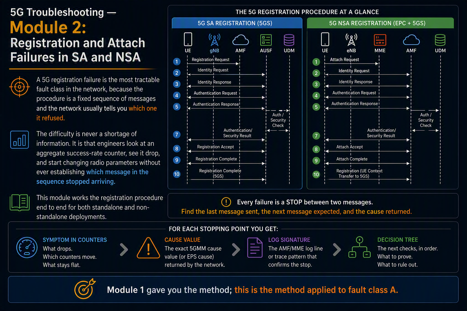
A 5G registration failure is the most tractable fault class in the network, because the procedure is a fixed sequence of messages and the network usually tells you which one it refused. The difficulty is never a shortage of information. It is that engineers look at an aggregate success-rate counter, see it drop, and start changing radio parameters without ever establishing which message in the sequence stopped arriving.
This module works the registration procedure end to end for both standalone and non-standalone deployments. For each stopping point you get the symptom as it appears in counters, the cause value the network returns, the log signature that confirms it, and the decision tree that follows. Module 1 gave you the method; this is the method applied to fault class A.
In this module
- Part 1 — What actually counts as a registration failure
- Part 2 — The SA registration flow and where counters peg
- Part 3 — Stopping point 1: RACH and the UE that never appears
- Part 4 — Stopping point 2: RRC setup rejected or timed out
- Part 5 — Stopping point 3: RRC succeeds, NGAP does not
- Part 6 — Stopping point 4: authentication and security
- Part 7 — Stopping point 5: Registration Reject and the 5GMM causes
- Part 8 — NSA: the EN-DC attach and SgNB addition
- Part 9 — Vendor counter mapping
- Part 10 — The full decision tree
Part 1 — What actually counts as a registration failure
Before measuring anything, be precise about which procedure you are talking about. Four distinct registration types exist in 5G, and they fail for different reasons:
| Registration type | When it happens | Typical failure driver |
| Initial | UE powers on, or moves from a non-allowed area | Subscription, provisioning, coverage |
| Mobility update | UE enters a TA not in its TAI list | TA list configuration, neighbor planning |
| Periodic | T3512 expires during inactivity | Rare; usually core-side or coverage at rest |
| Emergency | Emergency service with no valid subscription | Policy configuration on the AMF |
A spike that turns out to be periodic registration updates failing at 03:00 is a completely different investigation from initial registrations failing at the evening busy hour. Split the counter by registration type before you do anything else. If your OSS does not expose that split, the NAS trace does.
Second point of precision: a UE that fails registration and immediately succeeds on retry is not the same fault as a UE that cannot register at all. The first is a capacity or transient problem and shows up as a dip in success rate with normal attach volume. The second shows up as repeated attempts from the same SUPI, and the retry pattern itself is diagnostic — a UE backing off on T3502 for twelve minutes has hit the attempt counter limit, which means five consecutive failures.
Part 2 — The SA registration flow and where counters peg
This is the same ladder from Module 1, annotated with where the standard performance counters increment. The pegging points matter: they tell you which counter will move when a given message stops arriving, and therefore which counter to look at first.
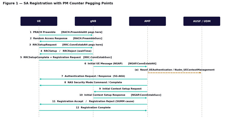
Figure 1 — SA registration with PM counter pegging points. Counter names follow 3GPP TS 28.552; vendor equivalents are in Part 9.
Three counter pairs bracket the whole procedure, and comparing them isolates the failure to a segment before you look at any cause value:
| Counter pair | Covers | If this pair is the one that drops |
| RACH.PreambleAtt / .PreambleSucc | Msg1 to Msg2 | Uplink coverage, PRACH configuration, preamble collision |
| RRC.ConnEstabAtt / .ConnEstabSucc | Msg3 to RRCSetupComplete | Admission control, T300 expiry, downlink coverage on Msg4 |
| NGAP.ConnEstabAtt / .ConnEstabSucc | Initial UE Message to Initial Context Setup | NG transport, AMF availability, slice availability |
The logic is subtraction. If RACH success is healthy and RRC success has fallen, the problem sits between Msg3 and RRCSetupComplete. If both are healthy and NGAP has fallen, the RAN is doing its job and the problem is on N2 or beyond. This single comparison eliminates two thirds of the search space in about a minute, and it works on every vendor because the segments are defined by the protocol rather than by the OSS.
The RACH pair deserves particular attention because it fails silently. A UE that never gets a Random Access Response simply gives up and reselects — no reject, no cause code, nothing in the AMF logs. RACH preamble planning covers root sequence allocation and the collision behavior that produces this, and NR initial access — cell search, SSB and random access covers the synchronization steps that precede it.
Part 3 — Stopping point 1: RACH and the UE that never appears
Symptom
RACH.PreambleAtt is normal or elevated, RACH.PreambleSucc is depressed. RRC.ConnEstabAtt is low relative to historical volume, because attempts that never get past Msg2 never peg an RRC attempt. Customer reports say “no service” or “searching” rather than “slow”.
The three mechanisms
Uplink coverage limitation. The preamble is transmitted at a power derived from the measured downlink path loss, and if the UE is at the edge of a cell whose downlink is stronger than its uplink can match, the preamble never arrives at usable power. This is the classic uplink-downlink imbalance, and it is far more common in 5G mid-band than it was in LTE because the downlink benefits from massive MIMO gain that the uplink cannot reciprocate.
Preamble collision. Two UEs choose the same preamble in the same RACH occasion, the gNB decodes one, and the other fails contention resolution at Msg4. At low load this is negligible. In a stadium, a station, or after a cell outage when hundreds of UEs re-access simultaneously, it dominates. The signature is a RACH success rate that degrades with load rather than with distance.
Timing advance out of range. The maximum cell radius supported by the PRACH format is a hard limit set by the preamble format and cyclic prefix. A UE beyond that distance produces a preamble the gNB cannot place in time, and it is discarded. This appears as a hard geographic boundary rather than a gradual degradation, and it is common on coastal or desert cells where propagation carries much further than the planner assumed.
Triage steps
- Split RACH success by preamble format and by SSB beam index. A single failing beam points to a blocked or misaligned sector, not to a cell-wide problem.
- Compare the uplink and downlink link budgets at the reported failure distance. If the downlink RSRP at the failure point is better than -110 dBm, coverage is not the answer and you should move to collision or timing.
- Check the ratio of contention-based to contention-free attempts. A rising contention-based share under load confirms collision.
- Verify the PRACH configuration index and the resulting cell radius limit against the actual cell footprint.
- Check the uplink noise floor. External interference on the uplink raises the effective threshold and produces exactly this signature with no configuration change involved.
A RACH failure produces no cause code anywhere. If your investigation depends on reading a reject, you will conclude nothing is wrong.
Part 4 — Stopping point 2: RRC setup rejected or timed out
Here the UE reached the gNB and the gNB either refused it or the UE never received the answer. The distinction between those two is the whole of this section, and the standard counters separate them for you.
| Counter | Meaning | What it points at |
| RRC.ConnEstabFail.Rej | gNB sent RRCReject | Admission control, licence limit, deliberate overload action |
| RRC.ConnEstabFail.T300Expiry | UE gave up waiting | Msg4 not received — downlink coverage or contention resolution |
| RRC.ConnEstabFail.Other | Everything else | Usually protocol errors or internal node faults |
If rejections dominate
An RRCReject carries a waitTime, and the gNB sends it because it decided to. Something on the node is refusing admission, and the candidates are finite: the configured maximum of RRC-connected users has been reached, a licence limit on connected users or throughput is capping the cell, baseband processing resources are exhausted, or an overload protection feature has activated because the node is under pressure from another direction.
The differentiator is time correlation. A licence limit produces a hard ceiling — the connected-user count flatlines at a suspiciously round number and rejections begin exactly there. Overload protection produces a ragged pattern that tracks load. And a maximum-users limit that was never a problem before, appearing suddenly, almost always means something changed the connected-user profile: a firmware rollout that altered inactivity timers, or a new device population that stays connected longer.
If T300 expiry dominates
The UE sent Msg3 and never got a usable Msg4. Because the UE gives up on its own timer, the gNB may not log a failure at all — from the node’s perspective it answered. Look for the asymmetry: RRC attempts pegged, no corresponding success, no reject sent.
Two mechanisms produce this. Downlink coverage marginal at the cell edge, where Msg3 arrives after power ramping but Msg4 cannot be decoded — check whether failures cluster at low RSRP. Or contention resolution failure, where two UEs collided at Msg1, both sent Msg3, and only one is addressed in Msg4; the other times out. That second case is a RACH problem presenting as an RRC problem, which is exactly why the counter comparison in Part 2 comes before cause analysis.
Triage steps
- Split RRC.ConnEstabFail by sub-cause. This one split resolves most investigations at this stopping point.
- For rejections: check connected-user count against the configured and licensed maximum, at the failure timestamps rather than as a daily average.
- For T300 expiry: plot failures against reported RSRP. A coverage-driven distribution is skewed to the cell edge; a collision-driven one is not.
- Check the establishment cause distribution in Msg3. A surge in one cause — mo-Signalling, for instance — points at a device population doing something new rather than at the network.
- Confirm the T300 value configured on the cell. An aggressive value causes UEs to abandon attempts the network would have answered.
Part 5 — Stopping point 3: RRC succeeds, NGAP does not
The RAN completed its part. RRC.ConnEstabSucc pegged, the NAS Registration Request was carried in RRCSetupComplete, and the gNB forwarded it to the AMF as an Initial UE Message. Then nothing. This is the cleanest fault class in the whole procedure, because the RAN has proven itself healthy and the search space collapses to transport and core.
What to check, in order
- SCTP association state on N2. If the association is down or flapping, every UE on that gNB fails identically and the scope will be the whole node, not a cell.
- AMF selection. The gNB picks an AMF from the ones it has NG Setup with, guided by the 5G-S-TMSI or the requested NSSAI. If the UE requests a slice this AMF does not serve and no alternative is configured, the request dies here.
- AMF load and admission. An AMF at capacity may drop rather than reject, particularly during a registration storm after an outage elsewhere.
- NG Setup state. A gNB whose NG Setup with a given AMF has failed will not forward to it at all. This is visible on the node long before it is visible in a KPI.
- Transport between the gNB and the AMF — this is ordinary IP transport and fails in ordinary ways, including MTU problems that only affect the larger NGAP messages.
The scope test from Module 1 is decisive here. If one gNB is affected and its neighbors are healthy, the fault is that node’s N2 or its transport. If every gNB homed on one AMF is affected, the fault is the AMF. If the affected gNBs share nothing except a transport path, you have found your answer without touching a single core log.
Knowing which network function owns which message is what makes this section fast rather than slow. The AMF, SMF and UPF breakdown maps each message in Figure 1 to the element that generates it, and control and user plane separation explains why a signaling failure here says nothing at all about whether the user plane would have worked.
Part 6 — Stopping point 4: authentication and security
Authentication failures are unambiguous, which makes them satisfying to diagnose. The network either accepted the UE’s response or it did not, and it says so.
| Failure | Message | Cause |
| Authentication Reject | AMF to UE | RES* mismatch: wrong K or OPc in the UDM, or the SIM was provisioned against a different key set |
| Auth failure, SQN | UE to AMF, cause #21 | Sequence number out of sync — the UDM and the SIM disagree on the counter; usually self-healing via resync |
| Auth failure, MAC | UE to AMF, cause #20 | The UE could not verify AUTN. In practice this means a network configuration error, or a false base station |
| Security Mode Reject | UE to AMF | The UE cannot support the selected NAS algorithm. Rare, and almost always a device or configuration mismatch |
A single UE failing authentication is a provisioning problem and belongs with the subscriber management team, not with RAN. Many UEs failing authentication simultaneously is a UDM or AUSF problem, or a recent provisioning migration that mismatched key material for a batch of subscribers.
The MAC failure case is worth flagging for a different reason. It means the UE received an authentication challenge it could not verify as coming from a legitimate network. A handful of these is noise. A cluster of them in one geographic area, with no configuration change to explain it, is the signature a security team wants to know about.
Part 7 — Stopping point 5: Registration Reject and the 5GMM causes
The procedure reached the AMF, authenticated successfully, and the AMF then declined to register the UE. It tells you exactly why. These are the causes worth memorizing, grouped by what they actually mean rather than by number.
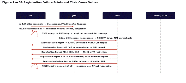
Figure 2 — SA registration failure points mapped to the cause value each one produces.
Subscription and identity
| Cause | Meaning | What to do |
| #3 | Illegal UE | SUPI not provisioned in the UDM, or authentication permanently failed. Check subscriber provisioning first, not the radio |
| #6 | Illegal ME | IMEI is barred in the EIR. Deliberate, and usually correct — stolen or non-type-approved device |
| #7 | 5GS services not allowed | Subscription does not include 5G. Check UDM access restriction data. Very common on migrated LTE subscribers |
Location and roaming
| Cause | Meaning | What to do |
| #11 | PLMN not allowed | Roaming agreement, or the PLMN is on the UE’s forbidden list from an earlier failure. Note that the forbidden list persists until reboot or SIM refresh |
| #12 | Tracking area not allowed | The TAI is not in the subscribed TA list. Check the TAC configured on the cell against the subscription profile |
| #13 | Roaming not allowed in this TA | Regional subscription restriction, working as designed |
| #15 | No suitable cells in TA | Cells barred, or a TAC misconfiguration on the gNB. A newly integrated site with the wrong TAC produces this for every UE |
Causes #11 and #12 have a property that makes them worse than they look: the UE stores the rejecting PLMN or TA in a forbidden list and will not retry until it reboots or the list is cleared. A misconfiguration that causes ten minutes of #12 rejections generates hours of customer impact, because the affected UEs stop trying. When you fix the root cause, the recovery curve will be far slower than the failure curve, and that is expected rather than evidence the fix did not work.
Capacity and slicing
| Cause | Meaning | What to do |
| #22 | Congestion | AMF overload control is active. A back-off timer is included; the UE will not retry until it expires. Check AMF load, and whether a registration storm elsewhere is the driver |
| #31 | Redirection to EPC required | The network is telling the UE to use LTE instead. Expected on subscribers without SA entitlement — not a fault unless it is unexpected |
| #62 | No network slices available | The requested NSSAI is not supported by this AMF, this gNB, or this subscription. Three places to check, and they disagree more often than you would like |
Cause #62 is the one that generates the most misdirected effort in enterprise deployments, because the customer reports total service failure while every radio KPI on the serving cell is green. The slice must be configured consistently on the subscription, the gNB and the AMF; a mismatch in any one produces this. Network slicing — one physical network, many virtual ones covers how the allowed NSSAI is negotiated, and QoS and 5QI covers what governs the traffic once registration succeeds.
Triage steps for any Registration Reject
- Aggregate rejects by cause value over the failure window. One dominant cause is a configuration fault; a flat distribution across many causes is usually normal background.
- Split by cell, by TAC, and by AMF. A cause confined to one TAC is a TAC configuration problem regardless of what the cause name suggests.
- Split by device model. A cause confined to one model is a capability or firmware issue, not a network fault.
- Correlate the start time with the change log. Causes #12, #15 and #62 are overwhelmingly caused by a configuration change rather than by degradation.
- For #22, check whether the AMF is genuinely overloaded or whether overload control triggered on a threshold that no longer matches the network’s size.
Part 8 — NSA: the EN-DC attach and SgNB addition
In non-standalone deployments there is no 5G registration at all. The UE performs an ordinary LTE attach to the EPC, and 5G is added afterwards as a secondary cell group. This means every NSA “5G not working” complaint is really one of two separate faults: the LTE attach failed, or the SgNB addition failed. They are diagnosed in completely different places.
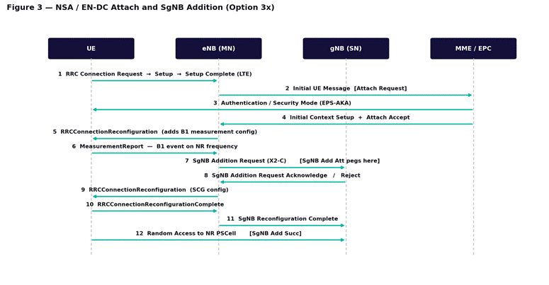
Figure 3 — NSA / EN-DC attach and SgNB addition. Steps 1 to 4 are pure LTE; 5G involvement begins at the B1 measurement configuration in step 5.
The consequence for triage is immediate. If the UE has no LTE service either, stop looking at 5G entirely — this is an LTE attach failure and the whole of the EPC procedure applies. If the UE has working LTE data but no 5G indicator, the attach succeeded and the failure is somewhere in steps 5 through 12.
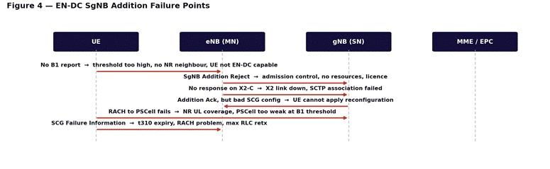
Figure 4 — EN-DC SgNB addition failure points, from missing measurement report through to SCG failure.
No B1 measurement report
The UE never reported an NR cell worth adding. Four candidates: the B1 threshold is set too aggressively for the actual NR coverage, no NR neighbor relation is defined on the LTE cell, the UE is not EN-DC capable or the capability was not signaled, or the NR cell genuinely is not there. Check the neighbor relation first — it is the most common and the easiest to verify.
SgNB Addition Reject
The gNB refused. This is the NR-side equivalent of an RRCReject and the causes rhyme: admission control, resource exhaustion, licence limits, or a requested configuration the gNB cannot support. Check the reject cause in the X2 message rather than inferring it.
No response on X2-C
The eNB sent the addition request and got nothing. X2 link down, SCTP association failed, or transport between the two nodes is broken. Every UE on that eNB-gNB pair fails identically, which makes the scope test trivial.
RACH failure to the PSCell
The addition succeeded on the network side and the UE could not access the NR cell. This is the most misdiagnosed EN-DC failure, and the mechanism is almost always the same: the B1 threshold is based on downlink measurement, but accessing the PSCell requires an uplink the UE may not have at that distance. The 5G downlink is visible; the 5G uplink is not. Raising the B1 threshold usually fixes it, at the cost of a slightly smaller 5G footprint.
SCG Failure Information
The UE was on the PSCell and lost it. The message carries a failure type — t310 expiry, random access problem, or maximum RLC retransmissions — and each points somewhere different. T310 expiry is NR coverage. Random access problem is uplink at the PSCell. Maximum RLC retransmissions usually indicates interference or a badly mismatched link adaptation.
The radio link failure timers behind SCG failure are the same T310, T311, N310 and N311 mechanics used in LTE — radio link failure in LTE covers how they interact. For the LTE attach half of an NSA fault, the basic LTE call flow and detach cause analysis in LTE apply directly, since in NSA the control plane is entirely LTE.
Part 9 — Vendor counter mapping
Counter names differ by vendor, but the measurement points do not — they are defined by the protocol. The table below gives the 3GPP TS 28.552 reference name and the vendor naming convention, so you can locate the equivalent in your own OSS.
| 3GPP TS 28.552 | Huawei (MAE-Access) | Ericsson (ENM) |
| RRC.ConnEstabAtt.sum | N.RRC.ConnReq.Att | pm-prefixed, RRC connection establishment attempt |
| RRC.ConnEstabSucc.sum | N.RRC.ConnReq.Succ | pm-prefixed, RRC connection establishment success |
| NGAP.ConnEstabAtt | N.NgSig.ConnEst.Att | pm-prefixed, NG signaling connection establishment |
| NGAP.ConnEstabSucc | N.NgSig.ConnEst.Succ | pm-prefixed, NG signaling connection success |
| QosFlow.EstabAtt.sum | N.PDUSession.SetupReq.Att | pm-prefixed, PDU session resource setup |
| RACH.PreambleAtt | N.RACH domain counters | pm-prefixed RACH counters |
Two things to be careful about here. First, Huawei composes 5G accessibility as a product of three ratios — RRC, NG signaling and PDU session — rather than as a single figure, which is genuinely more useful for troubleshooting because a fall in the product tells you which factor moved. Second, the Ericsson column gives the naming convention rather than exact 5G counter names; Ericsson’s LTE counters follow the pmRrcConnEstabAtt and pmRrcConnEstabSucc pattern and the 5G names follow the same construction, but confirm the exact strings against the PM counter reference for your software baseline before building a report on them.
For Nokia, counters are exposed through NetAct and organized into numbered measurement classes rather than descriptive names, so the mapping has to come from the counter reference for your release. The measurement points are identical; only the labeling differs.
Never build a KPI on a counter name you have not confirmed against your own software baseline. The measurement points are standard; the strings are not.
Part 10 — The full decision tree
Everything above, compressed into the order you should actually work it. This assumes you have already classified the fault as class A using Module 1.
Step 1 — Establish which deployment
- SA or NSA? In NSA, check whether LTE data works. If it does not, this is an LTE attach fault and the 5G procedure is irrelevant.
- Split the failure counter by registration type. Initial, mobility, periodic and emergency fail for different reasons.
Step 2 — Locate the segment
- Compare RACH attempt/success. If this pair has moved, go to Part 3 and stop.
- Compare RRC establishment attempt/success. If this pair has moved, split by sub-cause and go to Part 4.
- Compare NGAP establishment attempt/success. If this pair has moved and the two above are healthy, go to Part 5.
- If all three pairs are healthy but registrations still fail, the failure is at the NAS layer — authentication or Registration Reject. Go to Parts 6 and 7.
Step 3 — Read the cause, then scope it
Once you have a cause value, do not act on it until you have split it three ways: by cell or TAC, by device model, and over time against the change log. A cause value tells you what the network decided. The scope tells you why. Cause #12 confined to one TAC is a TAC configuration error; the same cause spread evenly across the network is a subscription data problem. Same code, completely different fix.
Step 4 — Confirm the fix against the symptom
Registration faults have an unusually slow recovery signature because of the forbidden-list behavior described in Part 7. After a fix, success rate recovers as UEs reboot or their forbidden lists age out, which can take hours. Do not judge the fix on the first fifteen-minute period, and do not stack a second change on top while the first is still recovering.
What comes next
Module 3 takes fault class B — sessions that establish and then drop — covering radio link failure, the T310/T311 mechanics, handover failure signatures, and how to read an RLF report. Later modules cover the three families of low-throughput causes and EN-DC-specific SCG failures in depth. If you need the underlying architecture, the 14-module Introduction to 5G course covers the air interface and core design this course assumes.