

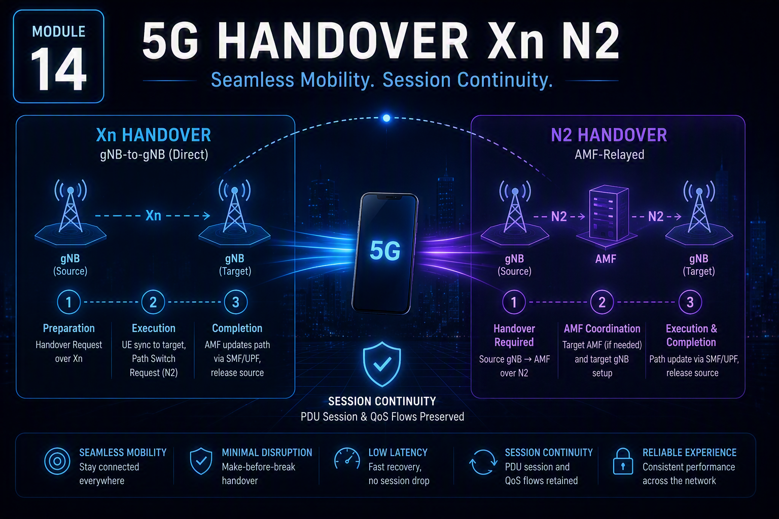
5G handover Xn N2 procedures are defined step-by-step in 3GPP TS 38.300 (overall description) and TS 23.502 Section 4.9 (detailed signaling flows) — and the specific messages exchanged at each step reveal exactly how much the disaggregated RAN (Module 5) and Service-Based Core (Modules 9–11) reshape what a handover has to coordinate, compared with LTE’s X2/S1 model.
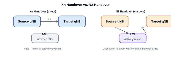
Diagram for Module 14
Diagram: 5G handover Xn N2 — direct gNB coordination versus AMF-relayed handover.
Xn Handover: gNB-to-gNB, without going through the core
The Xn handover, named after the Xn interface between neighboring gNBs (TS 38.423 defines the Xn Application Protocol, XnAP), is the most common, most efficient scenario. Per TS 23.502 Section 4.9.1.2, the procedure runs in three phases: Handover Preparation (source gNB sends a Handover Request over Xn, target gNB admits and responds with Handover Request Acknowledge), Handover Execution (source gNB commands the UE to synchronize to the target cell via RRCReconfiguration, target gNB sends a Path Switch Request toward the AMF over N2 to update the user-plane path), and Handover Completion (AMF updates the UPF’s N3 path via the SMF, source gNB is released). Critically, the AMF is informed but not deeply orchestrating — the two gNBs coordinate largely directly, minimizing how much signaling travels up into the core and back before the connection re-establishes.
N2 Handover: when the core needs to be more directly involved
The N2 handover, named after the N2 interface between gNB and AMF, is used per TS 23.502 Section 4.9.1.3 when there’s no direct Xn connectivity between source and target gNB, or when the handover requires a change of serving AMF. Here, the source gNB sends a Handover Required message to the AMF over N2; the AMF selects the target AMF if needed, and coordinates directly with the target gNB, relaying handover signaling that an Xn handover would have exchanged directly between the gNBs themselves. This makes N2 handovers structurally closer to LTE’s S1-based handover procedure (via the S1-MME interface) than Xn handovers are to anything in LTE’s model.
Session continuity: what has to survive the handover
A successful handover has to preserve the device’s active PDU sessions (Module 10) and their QoS Flows (Module 13). This connects directly to CUPS (Module 11): because user-plane forwarding (UPF) is architecturally separated from control-plane session management (SMF), a handover can often be handled by adjusting the UPF’s N3 path to route through the new gNB while the underlying PDU session remains logically continuous — via the Path Switch Request procedure in an Xn handover, or equivalent N2 signaling — rather than requiring the session to be torn down and rebuilt.
In scenarios crossing UPF service areas, the network may need to relocate which UPF instance actually serves the session, a more involved procedure than a simple radio-level handover, but one CUPS’s architecture is specifically designed to support more gracefully than a coupled EPC-style model would.
SN Status Transfer: not losing in-flight data
For bearers using RLC AM (Acknowledged Mode, covered in this site’s Engineering Deep Dives archive), the source gNB sends an SN Status Transfer message to the target gNB during handover, per TS 38.300, communicating the PDCP sequence number state so in-flight, not-yet-acknowledged packets aren’t silently dropped during the transition — directly relevant to the kind of RLC-mode troubleshooting covered in this site’s VoNR/VoLTE engineering post.
Inter-RAT and NSA-specific mobility considerations
Recall from Module 3 that many real-world deployments run in NSA (Option 3/EN-DC) mode. Mobility here involves additional considerations beyond a pure SA-to-SA gNB handover — managing the LTE anchor connection alongside the 5G secondary connection, and handling scenarios where a device falls back to LTE-only connectivity if 5G coverage becomes unavailable, a direct, practical consequence of the NSA/SA distinction from Module 3.
Bringing the course together
Handover is a fitting place to close this course: a successful handover depends on nearly everything covered across the previous thirteen modules working correctly together — the RAN’s ability to maintain radio connectivity through the transition (Modules 4–8), the core’s ability to preserve session and QoS state across it via N2/N4 signaling (Modules 9–11, 13), and the broader architectural choices — CUPS, Service-Based Architecture, the NSA/SA distinction — that determine how gracefully that transition happens. Understanding 5G as a precisely specified system, grounded in real 3GPP document numbers rather than approximate popular explanation, is what this course has aimed to build from Module 1’s IMT-2020 table onward.
This concludes the Introduction to 5G series. Readers looking to go deeper into specific protocol-level mechanisms may find this site’s Engineering Deep Dives category, covering LTE and 5G NR internals in comparable technical depth, a useful complementary reference.