
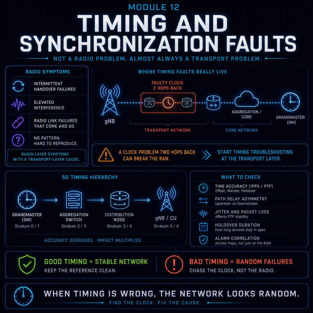
5G timing synchronization troubleshooting starts from an uncomfortable fact: the fault is almost never in the radio, and it almost always gets chased there first. A clock problem two hops back in the transport network produces symptoms — intermittent handover failures, elevated interference, radio link failures that come and go with no pattern — that are radio-layer symptoms with a transport-layer cause. Every module before this one assumed the timing reference feeding the RAN was correct. This module is about what happens when it isn’t.
Timing faults are disproportionately expensive to find because they fail the assumption every other fault class in this course relies on: that a symptom points back toward its cause through signaling you can trace. A phase-drifted clock does not send a message saying so. It just makes two neighboring cells’ frame boundaries stop lining up, and the first evidence anyone sees is a UE reporting interference that was never really there.
A radio engineer who has ruled out radio, transport and core still hasn’t ruled out the thing feeding all three their sense of time.
Why 5G needs synchronization at all
Two different properties of a network clock matter, and confusing them is the single most common error in this fault class.
| Property | What it guarantees | Who needs it |
| Frequency synchronization | All nodes’ clocks tick at the same rate — no drift over time, but no shared notion of “now” | Any TDM-based transport, and a baseline every RAN node needs regardless of duplex mode |
| Phase / time synchronization | All nodes agree on the actual time, typically to within microseconds | TDD frame alignment, carrier aggregation, handover measurement timing, and any feature comparing timestamps across cells |
Frequency sync alone is enough for FDD, where uplink and downlink never share spectrum. TDD is where phase sync becomes mandatory: every cell has to agree on exactly when to switch between uplink and downlink, because a neighboring cell transmitting downlink while yours is trying to receive uplink is straightforward self-interference, indistinguishable in the field from a genuine interference problem.
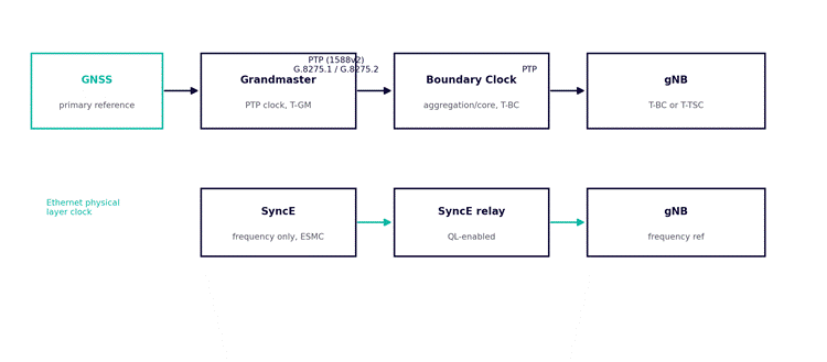
Figure 1. Two independent distribution paths reach the gNB: PTP for phase/time, SyncE for frequency. A fault in one can leave the other completely healthy.
The two distribution mechanisms, and why they fail differently
PTP (IEEE 1588v2) and SyncE solve different problems using different physical mechanisms, and a network typically runs both, layered, because SyncE cannot deliver phase and PTP alone is fragile against certain network conditions SyncE is immune to.
PTP — phase and time
PTP distributes time by exchanging timestamped messages between a grandmaster clock and every downstream node, correcting for measured path delay at each hop. ITU-T defines two relevant telecom profiles: G.8275.1, full timing support, where every node in the path is PTP-aware and corrects for its own delay (accurate, but requires PTP support end to end); and G.8275.2, partial timing support, where the network doesn’t fully support PTP hop by hop and the end node uses assisted partial timing support (APTS) — GNSS as primary reference with PTP as backup — to compensate.
PTP accuracy depends entirely on path symmetry: the assumption that the delay from grandmaster to node equals the delay from node to grandmaster. Any asymmetry — a different fiber length in each direction, an asymmetric patch, a firmware bug in an intermediate switch — translates directly into a fixed phase error that no amount of additional averaging removes, because it isn’t noise, it’s a constant offset.
SyncE — frequency only
SyncE recovers a frequency reference from the physical layer of the Ethernet signal itself — the same mechanism SDH/SONET used for clock recovery, adapted to Ethernet. It carries no time information at all, only frequency, and it uses ESMC (Ethernet Synchronization Messaging Channel) to advertise Quality Level (QL) so downstream nodes can select the best available source and avoid forming timing loops.
SyncE’s advantage is that it’s inherently immune to the packet-delay-variation problems that degrade PTP over a congested or asymmetric network — it rides the physical layer, not packets. Its limitation is equally fundamental: it cannot deliver phase, so it cannot solve TDD frame alignment on its own.
5G timing synchronization troubleshooting: the accuracy budget
3GPP TS 38.133 sets the phase accuracy requirement that matters most in the field: for TDD inter-cell synchronization where cells share spectrum, the requirement is tight — commonly cited as ±1.5µs between cells for the basic case, tighter still for features requiring inter-cell coordination such as CoMP or certain carrier aggregation configurations. FDD has no equivalent phase requirement at all, only frequency.
This is the number that turns a small, gradually accumulating phase error into a hard field fault. A clock drifting a few hundred nanoseconds a day looks like nothing for weeks — until cumulative offset crosses the ±1.5µs budget, and cells that were fine on Monday start producing intermittent interference on Friday with no configuration change in between.
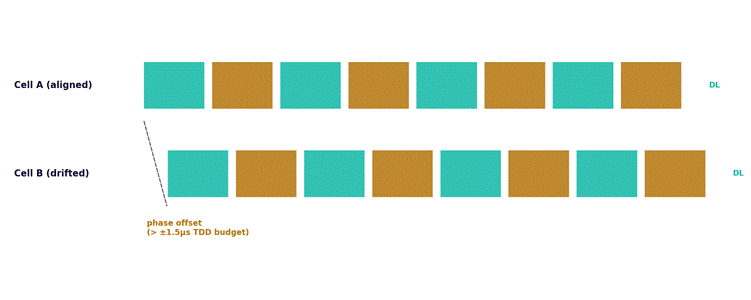
Figure 2. Two neighboring TDD cells whose downlink/uplink switching points have drifted apart. A UE near the boundary receives interference during what should be a quiet uplink slot.
Symptoms, and why they get chased at the wrong layer
| Field symptom | What it looks like | What it actually is |
| Elevated interference at a sector boundary, no new source found | RF interference investigation, neighbor audit, spectrum scan — all come back clean | TDD frame misalignment between neighboring cells — see Figure 2 |
| Handover failures concentrated between two specific cells | Looks like the handover neighbor relation or measurement configuration | Phase offset between the two cells’ clocks skews measurement timing enough to fail the procedure |
| Intermittent radio link failures, no RF pattern, no load correlation | Chased as radio link failure with no RF explanation found | Cumulative phase drift crossing the accuracy budget intermittently, correlating with time of day or temperature at the site, not with traffic |
| A single site’s problems started after unrelated fiber or router maintenance nearby | Dismissed as coincidental timing | New path introduced asymmetric delay — the maintenance event is the actual root cause |
The tell that separates this fault class from everything else in the course: every prior module assumed the fault would correlate with something — load, distance, device model, time of day tied to traffic. A timing fault often correlates with none of those and instead with something outside the RAN’s own telemetry entirely — temperature cycling on an outdoor GNSS antenna cable, a maintenance window on a transport link three hops away, a leap-second event. If nothing in the radio or core data explains a pattern, checking sync status is worth doing earlier than instinct suggests.
GNSS: the primary reference, and its own failure modes
Most grandmaster clocks derive their own reference from GNSS (commonly GPS), which introduces a failure domain with no RAN equivalent: signal jamming, spoofing, antenna cable degradation, and multipath from nearby structures. GNSS receivers report a lock status and typically a holdover state — the clock’s ability to maintain accuracy using its internal oscillator once GNSS is lost.
Holdover quality is the number that determines how much a GNSS outage matters. A high-quality oscillator (rubidium or better OCXO) can hold phase within budget for hours; a cheaper oscillator can drift out of the ±1.5µs TDD budget in minutes. The same GNSS outage is a non-event on one site and a field fault on another, purely because of which grandmaster hardware is deployed — worth knowing before treating two sites’ identical GNSS alarms as equally urgent.
Worked example
A cluster of four adjacent TDD sites reports intermittent handover failures between two specific cell pairs, recurring most afternoons and clearing overnight. RF investigation finds nothing: no interference source, no configuration difference, no load correlation strong enough to explain the pattern.
- Classify and scope. Failures are confined to two specific neighbor relations, not network-wide, and the time-of-day pattern doesn’t match traffic (peak busy hour is evening, not afternoon). A pattern with no RF or load correlation is the signal to check sync before continuing the RF investigation further.
- Check sync status. Both affected cells report PTP locked, no alarms. This initially looks like sync is ruled out — but “locked” confirms the PTP session is active, not that the resulting phase offset is within budget.
- Pull the actual phase offset, not just lock status. One cell shows a phase offset of roughly 1.3µs, within budget but close to it. The other, on a different transport path, shows negligible offset. The gap between them, at certain measurement windows, exceeds the inter-cell budget even though each individual cell is technically “locked.”
- Correlate with the time-of-day pattern. The drifting cell’s transport path runs through equipment in an unconditioned outdoor cabinet. Afternoon temperature swings shift the local oscillator’s frequency slightly — a known thermal effect — pushing accumulated phase error over the inter-cell threshold specifically during the hottest part of the day, and it relaxes back overnight as temperature drops.
- Fix and re-measure. The immediate fix is tightening the PTP profile’s correction aggressiveness on that path; the durable fix is cabinet thermal management, since the oscillator itself is operating outside its rated temperature range during peak heat.
Nothing about this fault would have surfaced from RF data alone — both cells’ radios were configured identically and performing exactly as specified. The investigation only converged once phase offset, not lock status, was actually measured.
Elimination order for a suspected timing fault
- Rule out an RF or capacity explanation the normal way first — this module extends Module 1‘s elimination order, it doesn’t replace it.
- If nothing RF-side explains the pattern, check sync alarms — but don’t stop at “locked”; pull the actual phase or frequency offset value.
- Compare the offset against the relevant 3GPP TS 38.133 budget for the feature involved — TDD frame alignment, CoMP, or carrier aggregation each have different tolerances.
- Check whether the pattern correlates with anything outside RAN telemetry: temperature, a known maintenance window on the transport path, a GNSS holdover event.
- If GNSS is implicated, check holdover oscillator grade before assuming the outage alone explains the magnitude of drift observed.
What comes next
Module 13 moves to the 5G core’s session layer: N4/PFCP session failures between the SMF and UPF — a fault domain where the radio and RRC layers can be entirely healthy while the user plane never actually forms.