

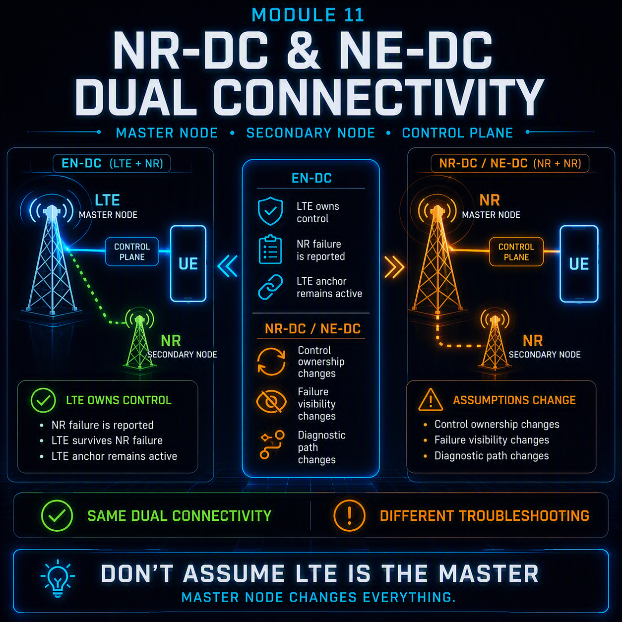
NR-DC troubleshooting starts from an assumption Module 8 made and this module removes: that the master node is LTE and the secondary node is NR. In EN-DC that is always true, and it shapes every diagnostic step — the LTE leg owns control, survives NR failure, and carries the report about it. Change which node is master, or make both legs NR, and several of those conclusions stop holding.
Two changes matter most. With a 5G core rather than an EPC, a master leg failure becomes recoverable through the secondary leg instead of ending the session — a mechanism EN-DC simply does not have. And when the secondary leg is FR2 rather than sub-6 GHz NR, beam management sits underneath the SCG and introduces failure modes that have no EN-DC equivalent at all.
In EN-DC, losing the master leg ends the session. With a 5G core, the secondary leg can rescue it — and that changes what a drop actually means.
In this module
- Part 1 — The four configurations, and which node owns control
- Part 2 — NR-DC: two NR legs, and what FR2 adds
- Part 3 — NE-DC: when NR is the master and LTE is secondary
- Part 4 — MCG failure recovery, the mechanism EN-DC lacks
- Part 5 — NR-DC troubleshooting: the failure types that carry over, and the ones that do not
- Part 6 — Beam failure recovery and its interaction with SCG failure
- Part 7 — Conditional PSCell addition and change
- Part 8 — What carries over unchanged from Module 8
- Part 9 — Counters, and the drop that is no longer a drop
- Part 10 — Worked example
- Part 11 — The full NR-DC troubleshooting decision tree
Part 1 — The four configurations, and which node owns control
Dual connectivity is one framework with four deployed variants. The differences that matter diagnostically are which node owns the RRC connection, which radio technology each leg uses, and — decisively — whether the core is an EPC or a 5G core.
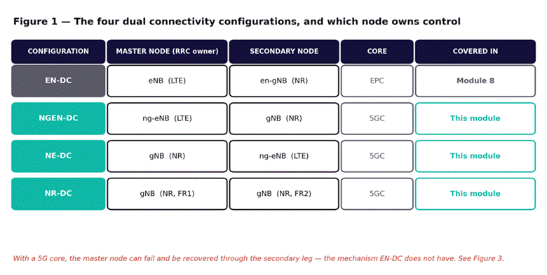
Figure 1 — The four dual connectivity configurations. Everything below the first row uses a 5G core, which is what enables MCG failure recovery.
EN-DC is Module 8’s subject: LTE master, NR secondary, EPC core. It remains the most widely deployed configuration and most non-standalone networks never move past it.
NGEN-DC keeps LTE as the master but connects to a 5G core. Structurally it behaves like EN-DC for radio faults, but it gains the core-side mechanisms described in Part 4.
NE-DC inverts the roles: NR is the master and LTE is the secondary. Part 3 covers why this matters more than it first appears.
NR-DC makes both legs NR, typically an FR1 master and an FR2 secondary. This is the configuration where the most genuinely new failure modes appear, because FR2 brings beam management into the secondary leg.
The single most useful thing to establish first on any dual connectivity fault is which configuration you are actually in. The symptom — a secondary leg that keeps disappearing — is identical across all four, and the diagnostic path is not.
Part 2 — NR-DC: two NR legs, and what FR2 adds
In NR-DC both legs are NR, and the usual deployment pairs a sub-6 GHz FR1 master with an FR2 millimeter-wave secondary. The FR1 leg provides stable, wide-area coverage and owns control; the FR2 leg provides the high data rate and is far more fragile.
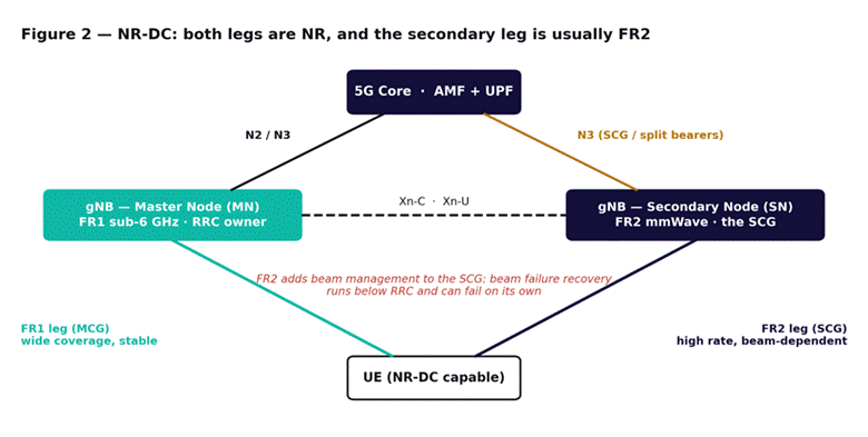
Figure 2 — NR-DC. The secondary leg is usually FR2, which brings beam management underneath the SCG.
The structural similarity to EN-DC is strong enough to be misleading. A master leg owns RRC, a secondary leg adds throughput, and the secondary leg can be added, changed and released without ending the session — all exactly as in Module 8. The FR2-specific behavior is where it diverges.
| FR2 property | Consequence for the SCG | Diagnostic implication |
| Directional beams rather than broad coverage | The link depends on beam alignment, not just path loss | RSRP alone does not predict whether the leg will hold |
| Blockage by obstacles, including the user | Losses are abrupt and may recover in seconds | Failures are bursty, not correlated with distance |
| Beam failure recovery runs in MAC, below RRC | A leg can recover without any RRC-visible event | RRC-level counters under-report FR2 instability |
| Much smaller cell radius | PSCell changes happen far more frequently | Mobility on the secondary leg dominates the fault profile |
The third row is the one that catches teams out. In EN-DC, an SCG problem produces an SCG failure report and a release. In NR-DC with FR2, the MAC-layer beam failure recovery procedure may fix the problem before RRC ever notices — so the leg is genuinely unstable while RRC-level statistics look acceptable. Part 6 covers what to measure instead.
Part 3 — NE-DC: when NR is the master and LTE is secondary
NE-DC inverts EN-DC: a gNB is the master node and an ng-eNB is the secondary. It appears in networks that have deployed a 5G core and standalone NR coverage but still want to use LTE capacity as a supplementary leg.
Two consequences follow directly, and both invert habits built on EN-DC:
- The control anchor is now NR. In EN-DC, the LTE leg was the reliable one and NR was the fragile addition. In NE-DC that is reversed — the NR leg carries RRC, so NR coverage problems now end sessions rather than merely degrading throughput. Everything Module 3 covers about radio link failure applies to the master leg here.
- The SCG failure report is the E-UTRA variant. Because the secondary leg is LTE, the failure information the UE sends about it uses the LTE structure rather than the NR one. The failure types are analogous but not identical, and tooling built to parse NR SCG failure reports will not read them.
The practical trap: a team experienced in EN-DC will instinctively treat the LTE leg as the safe anchor and the NR leg as the optional extra. In NE-DC that instinct produces exactly the wrong triage order. Confirm the configuration before applying any EN-DC reasoning.
Part 4 — MCG failure recovery, the mechanism EN-DC lacks
This is the most consequential difference in the module. In EN-DC, a master cell group failure is a radio link failure: the session ends and the UE begins re-establishment, exactly as Module 3 describes. With a 5G core, that is no longer necessarily true.
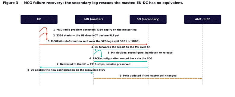
Figure 3 — MCG failure recovery. The UE reports the master leg’s failure over the secondary leg, and the session is preserved.
When the master leg fails and a working secondary leg exists, the UE does not immediately declare radio link failure. Instead it starts a recovery timer — T316 — and sends a master cell group failure report over the secondary leg. The network can then reconfigure, hand over, or release, and route the response back through the secondary leg. The session survives an event that in EN-DC would have been a drop.
| Outcome | What happened | How it appears in counters |
| Recovery succeeded | Report delivered over the SCG, reconfiguration applied, T316 stopped | No drop. The event may not appear at all unless specifically measured |
| No secondary leg available | Nothing to report over; the UE declares RLF immediately | An ordinary drop, exactly as in Module 3 |
| T316 expired | The report went out but no usable response returned in time | A drop — but a different root cause from a plain RLF |
| Secondary leg failed too | Both legs gone; recovery is impossible | A drop, with an SCG failure shortly beforehand |
The diagnostic consequence is significant. A network with MCG failure recovery working well will show a lower drop rate than the underlying radio conditions would suggest, because genuine master-leg failures are being absorbed. That is a real improvement in customer experience, but it also means the drop rate has stopped being a reliable proxy for radio health — the same measurement problem Module 8 identified for EN-DC, now applied to the master leg instead of the secondary one.
If master-leg failures are being silently recovered, your drop rate is measuring the recovery mechanism, not the radio.
Part 5 — NR-DC troubleshooting: the failure types that carry over, and the ones that do not
Module 8 established six SCG failure types. All six still apply, with the same meanings and the same triage. NR-DC and NE-DC add several more, and those additions are where this module’s diagnostic value sits.
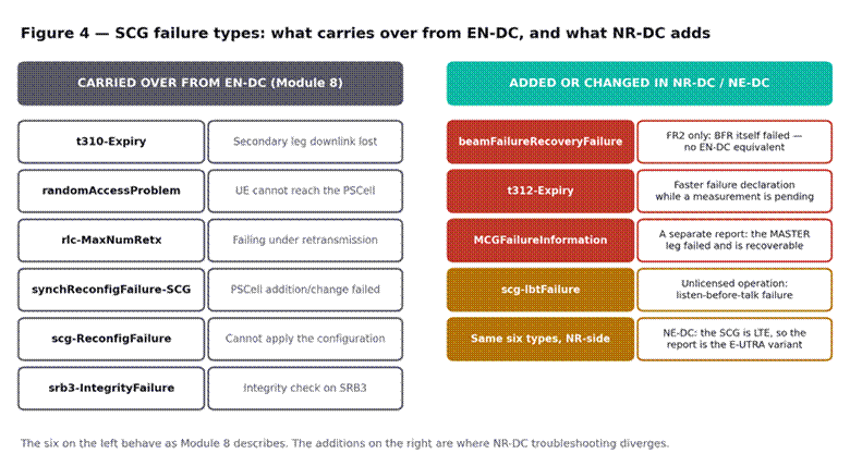
Figure 4 — What carries over from EN-DC and what is new. The left column is Module 8 material; the right column is where NR-DC diverges.
The additions that matter most
Beam failure recovery failure. FR2 only, and it has no EN-DC counterpart. The UE detected beam failure, attempted the recovery procedure, and the recovery itself failed. This is a distinct finding from a plain link failure: it says the beam management configuration, not the link budget, is the thing to examine. Part 6 covers it.
T312 expiry. A shorter timer that lets the UE declare failure faster while a measurement report is already pending, rather than waiting out the full T310. Where it is enabled, it changes the timing profile of failures — failures declared on T312 are not a new fault, they are the same faults surfacing sooner.
Master cell group failure information. Strictly this is a separate report rather than an SCG failure type, but it belongs in the same diagnostic picture: it is the mechanism from Part 4, and the failure types it can carry mirror the SCG list. Treat it as its own category — it describes the master leg, not the secondary one.
Listen-before-talk failure. Appears where the secondary leg operates in unlicensed spectrum. The leg failed because it could not gain channel access, which is a coexistence finding rather than a coverage or configuration one.
Part 6 — Beam failure recovery and its interaction with SCG failure
Beam failure recovery is a MAC-layer procedure. When the UE detects that its serving beams have degraded past a threshold, it identifies a candidate beam and attempts recovery through a dedicated random access procedure — all without RRC involvement.
Three outcomes are possible, and they produce very different evidence:
- Recovery succeeds. The leg continues on a new beam. RRC sees nothing. Repeated successful recoveries mean an unstable link that no RRC-level counter will report.
- Recovery fails and is reported. The UE sends an SCG failure report with the beam failure recovery failure type, which is the clearest possible signal that the fault is beam-specific rather than general coverage.
- No candidate beam is found. Recovery cannot even be attempted, and the failure surfaces as an ordinary link failure — indistinguishable from coverage loss without the beam-level detail.
What to measure: beam failure detection and recovery attempt counts, not just SCG failure counts. A cell with a high recovery attempt rate and a low failure rate has an unstable but self-healing FR2 link — the throughput consequences are real even though nothing is failing. This is the FR2 equivalent of the SCG retention argument Module 8 makes for EN-DC.
Part 7 — Conditional PSCell addition and change
Conditional PSCell addition and change applies the same principle to the secondary leg that conditional handover applies to the master leg: prepare candidate cells in advance, give the UE the execution condition, and let it act without waiting for a command. Conditional handover in 5G NR covers the underlying mechanism.
It removes the same failure mode — a command lost on a degrading link — and it matters more on FR2 than anywhere else, because FR2 links degrade abruptly enough that the command window is genuinely short. What it does not remove is the target still having to admit the UE, and the UE still having to complete random access on the target.
It also brings the same cost as conditional handover: multiple candidate cells hold prepared resources for a UE that will use at most one. On FR2, where PSCell changes are frequent, that over-preparation is proportionally larger. Track the ratio of preparations to executions as a KPI in its own right, exactly as Module 7 recommends for conditional handover.
Part 8 — What carries over unchanged from Module 8
Most of Module 8 applies directly, and repeating it here would waste your time. Specifically, these transfer without modification:
- The six original failure types and their triage logic — split by type before splitting by anything else.
- The downlink and uplink imbalance argument. The B1 threshold controls addition based on a downlink measurement while the uplink must sustain the result. On FR2 the imbalance is more severe, not less.
- Splitting failures by device model, which identifies capability faults quickly. NR-DC band combination support varies at least as much as EN-DC support does.
- The secondary leg retention metric. Time spent with the secondary leg active, as a proportion of connected time, remains the single most useful constructed measurement.
- Bearer option consequences. Which bearer type is configured still determines what the user loses when the secondary leg goes.
If any of those are unfamiliar, read Module 8 first — this module assumes them.
Part 9 — Counters, and the drop that is no longer a drop
Module 8 argued that standard KPIs hide EN-DC secondary leg failures because nothing drops. NR-DC extends that problem to the master leg, for a different reason: master leg failures that are successfully recovered also do not drop.
| Standard KPI | What it now misses | Measure this instead |
| Session drop rate | Master leg failures absorbed by MCG recovery | MCG failure report count, and recovery success rate |
| Secondary leg failure rate | FR2 instability healed at MAC level | Beam failure detection and recovery attempt rate |
| Handover success | PSCell changes are not handovers | PSCell change attempts and successes, by target |
| Accessibility | Measured on the master leg only | Secondary leg addition success, separately |
| Average throughput | Blends periods with and without the secondary leg | Throughput conditioned on the secondary leg being active |
The first row is the new one. A network where MCG recovery is working will look better on drop rate than its radio conditions justify. That is a genuine benefit, but it means a rising master-leg failure count can be entirely invisible until the recovery mechanism itself starts failing — at which point drops appear suddenly, with no preceding trend to have warned anyone.
Counter names differ by vendor while the measurement points do not. TS 28.552 defines where each one increments, and the NR-DC and MCG recovery counters are relatively recent additions — confirm they exist in your software baseline before designing a report around them.
Part 10 — Worked example
An operator running NR-DC on an FR1 macro layer with FR2 small cells in a stadium reports that peak throughput during events is far below design, though no KPI shows a problem. Drop rate is low, secondary leg addition success is above 95 percent, and FR2 cell availability is 100 percent.
Constructing the missing metric. Secondary leg retention — the proportion of connected time with the FR2 leg active — comes out at 34 percent during events. Devices are spending two thirds of their time on FR1 alone, which explains the throughput shortfall precisely.
Why addition success looked fine. Addition succeeds over 95 percent of the time. It is also being attempted constantly: devices add the FR2 leg, hold it briefly, lose it, and add it again. A high success rate on a very high attempt count was being read as health when it was actually churn.
Finding the mechanism. Beam failure recovery counters — not previously collected — show a very high recovery attempt rate with a moderate failure rate. The FR2 links are degrading constantly and mostly healing themselves at MAC level, which is why RRC-level statistics looked acceptable and why SCG failure counts were unremarkable.
The cause. During events the FR2 small cells are serving a dense standing crowd, and human bodies block millimeter-wave paths effectively. Beams are being blocked and re-acquired continuously. This is not a configuration fault — it is the physics of FR2 in a crowd.
The response. Two changes. Increasing the number of candidate beams configured for recovery reduces the cases where no candidate is found, improving recovery success. Enabling conditional PSCell change lets devices move between FR2 cells without waiting for commands that frequently arrive too late on a blocked link. Retention rises from 34 to around 60 percent. The remainder is a siting question — more FR2 cells at different heights and angles to provide path diversity — not a parameter one.
What made it findable: measuring retention rather than success rate, and then collecting beam-level counters that were not part of the standard report. Every existing KPI was accurate and every one of them was measuring something other than the problem.
Part 11 — The full NR-DC troubleshooting decision tree
Step 1 — Establish the configuration
- Determine which of the four configurations is deployed. EN-DC sends you to Module 8; the others continue here.
- Identify which node is the master. In NE-DC it is NR, which inverts the usual triage order.
- Identify whether the secondary leg is FR1 or FR2. FR2 brings beam management into scope.
Step 2 — Separate master leg from secondary leg
- Secondary leg failing while the session continues: the Module 8 framework applies, extended by Part 5.
- Master leg failing: check whether MCG failure recovery is configured and whether it is succeeding.
- Drops appearing suddenly with no preceding trend: suspect MCG recovery that was working and has stopped.
Step 3 — Split failures by type
- The six original types: apply Module 8’s triage unchanged.
- Beam failure recovery failure: go to Part 6. This is beam configuration, not link budget.
- T312 expiry: not a new fault. The same faults are being declared sooner.
- Listen-before-talk failure: unlicensed coexistence, not coverage.
- Master cell group failure information: this describes the master leg. Treat it separately.
Step 4 — On FR2, measure below RRC
- Collect beam failure detection and recovery attempt counts, not just SCG failure counts.
- A high recovery attempt rate with low failure rate means an unstable but self-healing link — real throughput loss with no failure signal.
- Check whether candidate beam configuration is sufficient before concluding the site needs more cells.
Step 5 — Judge against retention
- Measure secondary leg retention over a full representative period, not success rate.
- Distinguish churn from health: a high success rate on a very high attempt count is churn.
- Confirm against throughput conditioned on the secondary leg being active, which is what the customer actually experiences.
What comes next
Module 12 moves to a fault class that sits outside the radio entirely: timing and synchronization, where a clock problem in the transport network produces symptoms that look like interference, handover failure and radio link failure — and gets chased at the radio layer for days. The complete index is on the 5G Troubleshooting Guide, and the architecture this course assumes is covered in the 14-module Introduction to 5G course.