

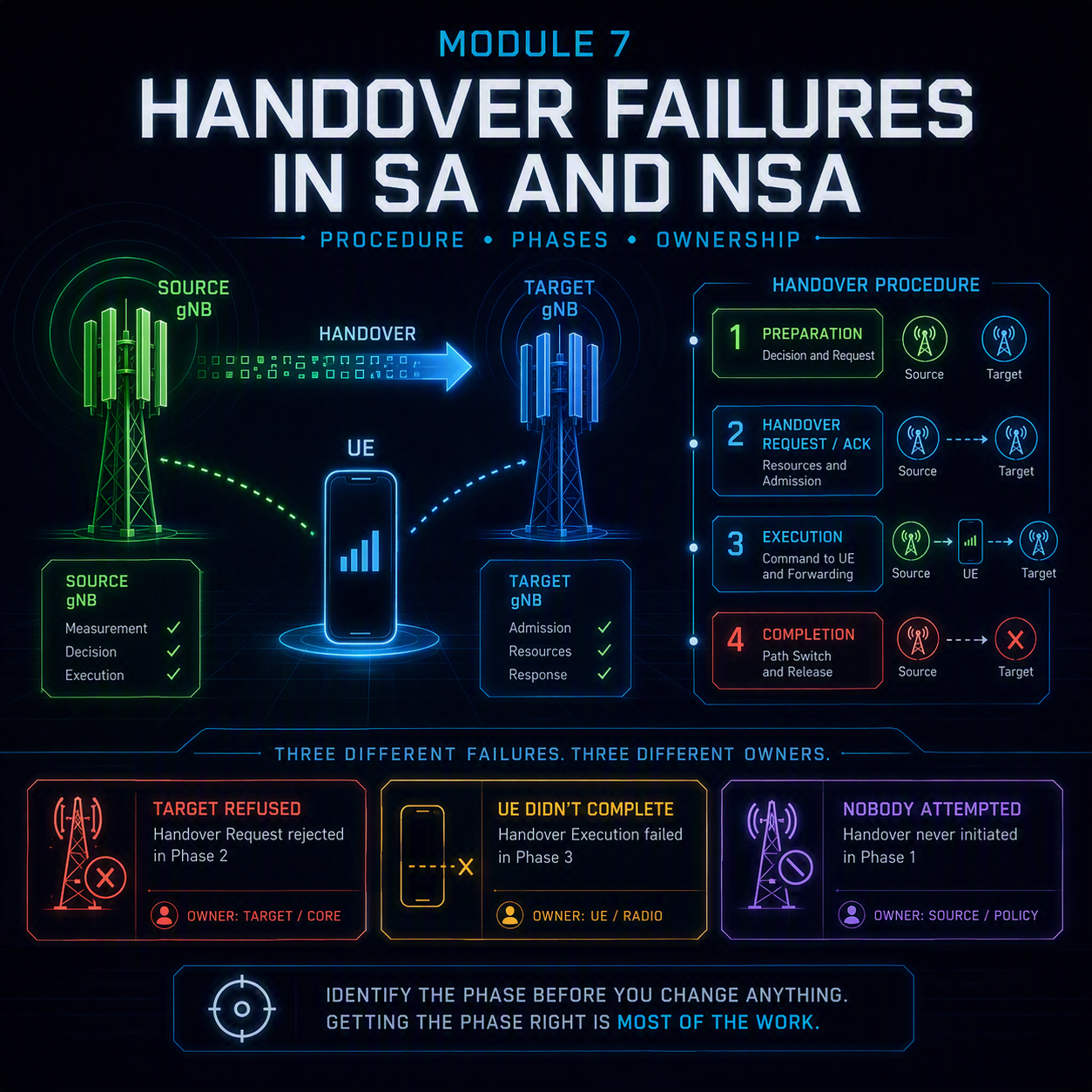
A 5G handover failure is the fault class that punishes aggregate thinking. A cell showing a 98 percent handover success rate can be losing every third session on one neighbor pair, on one route, at one time of day — and the cell-level number will never show it. Module 3 introduced the three classic signatures from the radio side. This module works the procedure itself: what each node is doing at every step, which message carries the failure, and which of the four phases the failure actually sits in.
That distinction matters more than any parameter. A handover that the target refused, a handover the UE never completed, and a handover that nobody ever attempted are three different faults with three different owners, and only one of them is fixed by touching mobility thresholds. Getting the phase right before touching anything is most of the work.
The most expensive handover failure is the one that never appears in a handover counter, because it was never attempted.
In this module
- Part 1 — The four phases, and what each failure leaves behind
- Part 2 — Xn-based handover, step by step
- Part 3 — NG-based (N2) handover, and when it is used instead
- Part 4 — Preparation failures: when the target says no
- Part 5 — Execution failures: T304 and the UE that never arrives
- Part 6 — Completion failures: path switch and the silent ones
- Part 7 — The 5G handover failure that was never attempted
- Part 8 — Conditional handover, and which failures it removes
- Part 9 — Inter-RAT: EPS fallback and NSA mobility
- Part 10 — Counters for 5G handover failure, and the comparisons that matter
- Part 11 — Worked example
- Part 12 — The full decision tree
Part 1 — The four phases, and what each failure leaves behind
Every handover, whatever the interface, runs through the same four phases. Each one fails differently and each leaves different evidence, so naming the phase is the first diagnostic step.
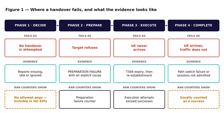
Figure 1 — Where a handover fails, and what the evidence looks like. Phase 1 and phase 4 failures are the two that hide from the handover KPIs.
The two shaded phases are the ones that cause the most wasted effort. A phase 1 failure never increments a handover attempt counter, because no attempt was made — it surfaces only as drops, or as users stuck on a distant cell. A phase 4 failure usually counts as a success, because the radio procedure completed; the user just has no data afterwards.
Phases 2 and 3 are the well-instrumented ones. Preparation failures produce an explicit cause value from the target, which is the single most useful piece of evidence in this fault class. Execution failures produce T304 expiry and a re-establishment attempt, which is the signature Module 3 covers as too-late and too-early handover.
Preparation failures tell you why. Execution failures make you infer it. Never treat the two as one number.
Part 2 — Xn-based handover, step by step
Xn handover is the direct case: the source gNB talks to the target gNB itself, and the core is only told afterwards. It is faster and more reliable than the alternative, and it is what should be happening for the overwhelming majority of intra-AMF mobility.
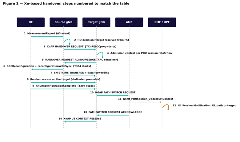
Figure 2 — Xn-based handover. Step numbers match the table below. The core is involved only from step 10 onward.
| Step | What happens | What it tells you when it fails |
| 1 | UE sends a MeasurementReport, normally on an A3 event | No report means phase 1 — go to Part 7 |
| 2 | Source resolves the reported PCI to a target cell and node | Wrong resolution is PCI confusion or a stale ANR relation |
| 3 | HANDOVER REQUEST over Xn; the preparation timer starts | No Xn relation forces the N2 path instead — see Part 3 |
| 4 | Target runs admission control per PDU session and QoS flow | Partial admission here becomes a phase 4 problem later |
| 5 | Target returns an ACKNOWLEDGE carrying the RRC container | A FAILURE instead is phase 2 — read the cause (Part 4) |
| 6 | Source sends RRCReconfiguration; T304 starts on the UE | If the UE never receives it, it stays on a dying source cell |
| 7 | SN status transfer and data forwarding to the target | Missing forwarding shows as a data gap, not a failure |
| 8 | UE performs random access on the target | Failure here is uplink, not mobility — see Part 5 |
| 9 | UE sends RRCReconfigurationComplete; T304 stops | This is the moment the handover is radio-complete |
| 10 | Target asks the AMF to switch the downlink path | Failure here is phase 4 — radio moved, traffic did not |
| 11–12 | AMF asks the SMF to update the session; N4 reprograms the UPF | Session-level failures land here, not in any RAN counter |
| 13 | AMF acknowledges the path switch | Partial acknowledgement means some flows were not moved |
| 14 | Target tells the source to release the UE context | Failure here leaks context, and it is rarely user-visible |
The structural point is that steps 1 to 9 are radio and steps 10 to 14 are core. A handover that fails after step 9 is not a mobility problem at all, however it looks on a mobility dashboard. The baseline procedure is covered in mobility and handover — Xn, N2 and session continuity, and the session machinery behind steps 11 and 12 in the AMF, SMF and UPF breakdown.
Part 3 — NG-based (N2) handover, and when it is used instead
When there is no usable Xn relation between source and target, the handover is routed through the AMF instead. It works, but it is slower — more nodes, more messages, more time between the decision and the execution — and at speed that extra latency is the difference between a handover and a drop.
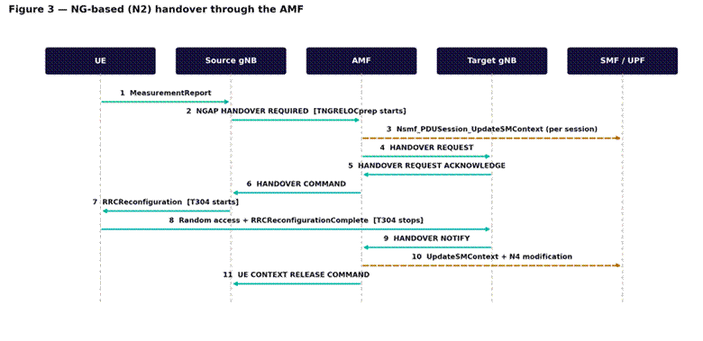
Figure 3 — NG-based (N2) handover. The AMF mediates, and the SMF is involved before execution rather than after.
N2 handover is correct and expected in several situations: between gNBs served by different AMFs, across an area where Xn is deliberately not deployed, and in any inter-RAT case. What it should not be is the default for neighboring cells in the same cluster.
This is worth auditing directly. If a neighbor pair is executing N2 handovers when both cells sit under the same AMF and are physically adjacent, the Xn relation is missing or down, and the fix is to restore it rather than to tune anything. The same missing relation also converts recoverable radio link failures into dropped sessions, as Module 3 describes — one configuration gap producing two apparently unrelated symptoms.
Triage: for any neighbor pair with elevated failures, first establish which procedure it is actually using. A pair that should be on Xn and is not has a transport or configuration fault between the two gNBs, and no amount of threshold tuning will address it.
Part 4 — Preparation failures: when the target says no
A preparation failure is the most tractable 5G handover failure, because the target states a reason. The cause values group into four families, and each points at a different team.
| Cause family | What it means | Where the fix lives |
| Radio network layer | Target cannot serve this UE — no resources, unknown cell, unknown UE context | Capacity, or the neighbor and PCI configuration |
| Transport layer | The Xn or NG transport itself failed | IP transport between the nodes, not the RAN |
| Protocol | Malformed message, abstract syntax error, unexpected state | A software or interoperability defect — escalate to the vendor |
| Miscellaneous | Hardware failure, O&M intervention, unspecified | Check whether the target is in a maintenance state |
The three worth investigating first
- No radio resources available on the target. This is genuine admission control, and it means the target is congested. The handover system is working correctly; the capacity plan is not. Tuning mobility thresholds to steer traffic away is a workaround that moves the congestion rather than removing it.
- Unknown target cell or unknown UE context. The source asked for something the target does not recognize. This is almost always a stale neighbor relation or a PCI that resolves to the wrong node — a planning fault rather than a radio one.
- Transport-layer causes. These are not RAN faults at all. The Xn interface runs over ordinary IP, and it fails for the ordinary reasons covered in Module 5. A neighbor pair with transport-cause preparation failures needs a transport engineer, not a tilt change.
Triage steps
- Split preparation failures by cause value first, then by neighbor pair. One dominant cause across many pairs is systemic; many causes on one pair is a link problem.
- For resource causes, check the target’s PRB utilization and connected-user count at the time of failure. Confirm it was genuinely busy before treating it as capacity.
- For unknown-cell and unknown-context causes, audit the neighbor relation and the PCI it resolves to, in both directions.
- For transport causes, check the Xn transport path between the two nodes — packet loss, MTU and reachability — before touching anything in the RAN.
- For protocol causes, capture the message and raise it with the vendor. These are defects, not configuration.
Part 5 — Execution failures: T304 and the UE that never arrives
Once the UE receives the reconfiguration, T304 starts. The UE now has a fixed window to reach the target, and if it does not, it declares handover failure and falls back to re-establishment. No cause value is generated, which is why execution failures are harder to work than preparation failures.
What actually goes wrong between the command and the completion
| Failure point | Mechanism | Usual root cause |
| The UE never received the command | Source downlink already too weak to deliver it | Too-late handover: the decision came after the link was gone |
| Random access to the target fails | UE cannot reach the target on the uplink | Downlink and uplink imbalance, or preamble contention |
| Target is not actually viable | UE arrives, cannot hold the link, fails immediately | Too-early handover to a transient peak |
| UE arrives at a different cell | The prepared target was not the right one | PCI confusion, or a stale relation |
The second row is the one most often misread. Random access failure on the target is an access problem, not a mobility problem — the handover decision was fine, and the UE simply could not complete the access procedure. The preamble side of this is covered in RACH preamble planning and the procedure itself in NR initial access — cell search, SSB and random access. Handover uses a dedicated contention-free preamble where one is allocated, so contention failures here often mean the allocation was not made or not received.
T304 itself is a genuine trade-off. Too short, and UEs abandon handovers that would have completed a few tens of milliseconds later. Too long, and the UE spends that whole window unable to use either cell before starting recovery. Judge it against measured access times on the target rather than against a vendor default.
A UE that fails random access on the target did not suffer a mobility failure. It suffered an access failure during mobility.
Part 6 — Completion failures: path switch and the silent ones
The UE has arrived, the radio procedure has completed, and the counters have recorded a success. Then the path switch fails, or succeeds only partially, and the user has a connected device with no working data.
Two variants matter. In the first, the path switch itself fails and the downlink is never moved to the target, so traffic continues to be sent to a cell the UE has left. In the second, the target admitted only some of the PDU sessions or QoS flows during preparation, the handover proceeded on the admitted ones, and the rest were released — the user keeps data but loses a service, typically the one with the strictest QoS requirement.
The second case is why partial admission at step 4 is worth watching even though it produces a successful handover. Which flows survive is a QoS decision, covered in QoS and 5QI, and the flows most likely to be dropped are exactly the ones the customer notices.
How to catch these: compare handover execution success against session or bearer continuity across the same neighbor pair. A pair where handovers succeed but session counts fall on the target is a completion failure, and no radio counter will show it.
Part 7 — The 5G handover failure that was never attempted
This is the phase 1 case, and the reason drop investigations on highway clusters so often stall. Nothing failed, because nothing was tried. The evidence is entirely negative: a UE that sat on a degrading cell while a far better neighbor was available, and then dropped.
The four reasons a handover is never attempted
- The neighbor relation does not exist. The UE may not even be measuring the better cell, because it was never told to. ANR fills most of these gaps, but not on frequencies or bands the UE is not configured to measure.
- The trigger condition is never satisfied. The A3 offset and hysteresis are too high for the geometry, so the neighbor never becomes sufficiently better before the serving cell fails outright.
- Time-to-trigger outlasts the link. The condition is satisfied, but the UE must hold it for the configured duration. At speed, the source cell can become unusable inside that window.
- The measurement report is lost. The condition was met, the UE sent the report, and the uplink was already too weak to deliver it. This is the failure mode conditional handover exists to remove.
The diagnostic that settles all four is the RLF report, covered in Module 3. Its measurement results field records what the UE could see at the moment of failure. A neighbor 10 dB stronger than the serving cell at that moment proves a handover should have happened, and separates a mobility problem from a coverage problem in a single field.
Triage steps
- Pull RLF reports for the failing area and read the measurement results. Was a better cell available at the moment of failure?
- If yes, check whether a neighbor relation exists for that cell, in both directions.
- If the relation exists, compare the A3 offset and time-to-trigger against the actual UE speed on that route.
- Check whether the UE was configured to measure that frequency at all. An inter-frequency neighbor with no measurement configuration is invisible to the UE.
- Only after all four: consider whether the report was sent and lost, which points at the uplink budget rather than at mobility configuration.
Part 8 — Conditional handover, and which failures it removes
Conditional handover changes the order of operations. The target is prepared in advance and the UE is given the execution condition, so when the condition is met the UE acts on its own without sending a report and waiting for a command.
That removes one specific failure mode completely: the lost measurement report and the lost handover command. Both were single points of failure on a degrading uplink, and both disappear when the decision is delegated. Conditional handover in 5G NR covers the mechanism in full.
What it does not remove is everything else. The target still has to admit the UE during preparation, the UE still has to complete random access on the target, and the path switch still has to work. The failure moves rather than vanishing.
It also introduces a fault of its own: multiple targets are prepared and hold resources for a UE that will use at most one. Over-preparation shows up as resource pressure on candidate cells and as a preparation-to-execution ratio well above one. That ratio is worth tracking as a KPI in its own right on any cluster where conditional handover is enabled.
Part 9 — Inter-RAT: EPS fallback and NSA mobility
Two inter-RAT cases produce handover failures that look like intra-5G ones and are not.
EPS fallback for voice
Where a standalone network does not carry voice on NR, an IMS voice call triggers a move to LTE. The UE is connected to 5G, a 5QI 1 flow is requested, the gNB declines to serve it, and the UE is moved to LTE by handover or by release with redirection.
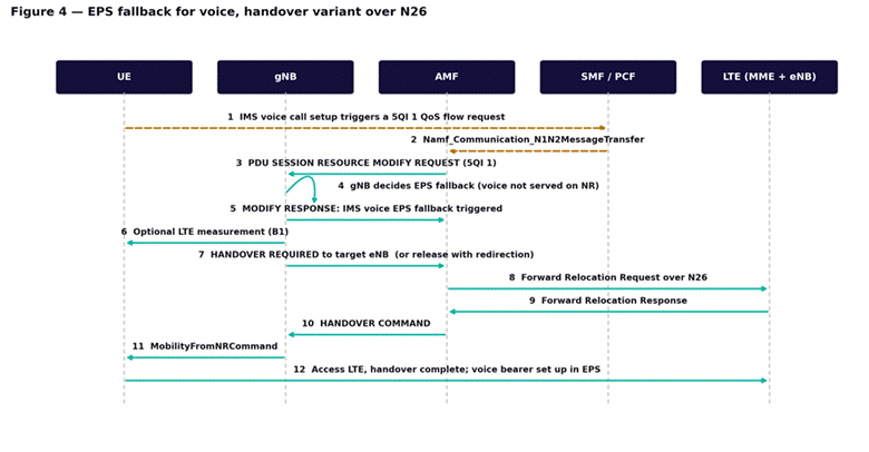
Figure 4 — EPS fallback for voice, handover variant over N26. Failure here is a failed call, not a failed data session.
Fallback failures are customer-visible in a way that data handover failures are not: the symptom is a call that takes several seconds to connect, or does not connect at all. The two variants behave differently under failure. The handover variant is faster but fails outright if the LTE target refuses. The redirection variant is slower — the UE must acquire and attach on LTE — but degrades more gracefully.
What to check first: whether LTE coverage exists at the point of fallback at all. A fallback into a hole is a failed call, and it will be reported as a 5G fault even though the 5G leg did exactly what it was configured to do. The basic LTE call flow covers the target side of the procedure.
Mobility in non-standalone
In NSA there is no 5G handover in the sense this module has used. Mobility is an LTE procedure on the LTE anchor, and the NR leg is added, changed or released around it. Those failures are a different fault class with different evidence, and they are covered in Module 8.
Part 10 — Counters for 5G handover failure, and the comparisons that matter
As in Module 3, single counters mislead and comparisons do not. Three rules cover most of it.
- Never read handover success at cell level. Split by neighbor pair. A cell at 98 percent can contain one pair at 60 percent, and the cell-level figure will never move enough to notice.
- Always separate preparation from execution. Preparation failures are the target refusing and come with a cause. Execution failures are the UE not arriving and do not. Different teams, different fixes, and averaging them together destroys both signals.
- Compare attempts against opportunities, not just successes. A pair with very few attempts and a perfect success rate may be failing at phase 1 — no attempts, no failures, and a KPI that looks ideal.
| Measurement point | What it isolates | Read it against |
| Handover preparation attempts and failures | The target’s admission decision | Cause value distribution, per neighbor pair |
| Handover execution attempts and successes | Whether the UE arrived | Preparation success — the gap is the execution loss |
| Intra-system handovers split by Xn and N2 | Which procedure the pair is using | Whether Xn should exist for that pair |
| Re-establishment attempts and successes | Recovery after execution failure | Execution failures — low recovery turns them into drops |
| Path switch requests and failures | Phase 4 | Execution successes — a gap here is invisible otherwise |
Counter names differ by vendor while the measurement points do not. 3GPP TS 28.552 defines where each one increments; Huawei uses its N.<Domain>.<Metric> convention and Ericsson a pm prefix, and Nokia places the equivalents in numbered NetAct measurement classes. Confirm the exact strings against the counter reference for your own software baseline before building a report on them.
Part 11 — Worked example
An operator reports that handover success across a metro cluster is 97.8 percent against a 99.2 percent target, with no obvious geographic pattern. Two rounds of A3 offset tuning have moved the number by less than a tenth of a percent.
Splitting by phase. Preparation success is 99.6 percent. Execution success is 98.2 percent. Most of the loss is in execution, so the target is not refusing — the UEs are not arriving. That alone rules out capacity and admission as the main cause, which is where the investigation had been focused.
Splitting by neighbor pair. Eleven pairs out of just over four hundred account for most of the execution failures. Those eleven all share one property: the target is one of three cells on a recently added mid-band layer.
Reading the evidence. RLF reports from failing UEs show the failure type as handover failure, with the target RSRP adequate at the moment of the command. So the target was strong enough on the downlink. The failures are concentrated at the far edge of those three cells, and the UEs that fail are disproportionately at high path loss.
The mechanism. The three mid-band cells have a downlink that reaches considerably further than the uplink can answer, for the array-gain reasons covered in massive MIMO and beamforming. UEs are being handed into cells they can hear but cannot reach, and the failure is at step 8 — random access on the target — not at the handover decision at all.
The fix. Raising the A3 offset for those three cells specifically, so that UEs hand in only where the uplink can sustain the connection. Cluster-wide A3 tuning had failed because the problem was on three cells and the change was being applied to four hundred. Execution success on the eleven pairs rose above 99 percent; the cluster figure followed.
What made it findable: splitting preparation from execution in the first ten minutes. Both rounds of earlier tuning had been driven by a single blended success rate that averaged a genuine uplink problem on three cells into four hundred healthy ones.
Part 12 — The full decision tree
Step 1 — Establish the phase
- Compare preparation attempts against execution attempts against successes. The gaps tell you which phase is losing sessions.
- If attempts are low relative to the drops being reported, suspect phase 1 and go to Part 7.
- If execution succeeds but sessions do not survive, suspect phase 4 and go to Part 6.
Step 2 — Split by neighbor pair before anything else
- Rank pairs by absolute failure count, not by rate. A pair with a 40 percent failure rate and nine attempts a day is not the problem.
- Check what the failing pairs have in common: a band, a target node, a direction, a time of day.
Step 3 — For preparation failures, read the cause
- Group by cause family. Radio network layer, transport, protocol and miscellaneous each go to a different team.
- Do not tune mobility parameters to route around a resource cause. That moves congestion; it does not remove it.
Step 4 — For execution failures, find out where the UE stopped
- Check whether the target is uplink-limited before assuming the decision was wrong.
- Check the dedicated preamble allocation for the pair.
- Use the RLF report failure type to separate too-late, too-early and wrong-cell, as in Module 3.
Step 5 — Check the procedure itself
- Confirm whether the pair is using Xn or N2. A pair that should be on Xn and is not has a transport or configuration fault.
- Confirm the neighbor relation is bidirectional. One-way relations fail in one direction only, which produces a confusing partial signature.
Step 6 — One change, then measure
- Change one parameter on the specific pairs that are failing, not across the cluster. Cluster-wide changes average out the effect you are trying to see.
- Allow a full day before judging. Mobility KPIs follow traffic patterns and a single busy hour proves nothing.
- Confirm against the original complaint — drops, or a customer report — rather than against the counter you changed.
What comes next
Module 8 takes the non-standalone side: EN-DC and SCG failure, where the NR leg fails while the LTE anchor holds the session and nothing appears in any drop counter. If you need the underlying architecture, the 14-module Introduction to 5G course covers the air interface and core design this course assumes, including mobility and handover — Xn, N2 and session continuity, which this module builds on directly.