

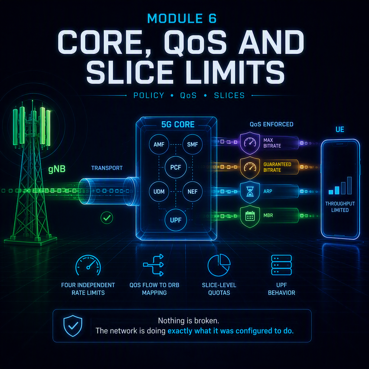
5G QoS troubleshooting is the last place anyone looks and frequently the place the answer is. A session can have an excellent radio link, a clean transport path, and still deliver a fraction of what it should — because somewhere in the core, a policy decision capped it, and policy decisions do not appear in radio or transport counters.
This module completes fault class C. Modules 4 and 5 covered the radio and the transport path; what remains is everything the core enforces: the four independent rate limits, the QoS flow to DRB mapping that quietly discards your traffic differentiation, slice-level quotas, and the UPF itself. The distinguishing feature of every fault in this module is that nothing is broken. The network is doing exactly what it was configured to do.
A policy ceiling is not a failure. It is the network working correctly, to a configuration nobody remembers making.
In this module
- Part 1 — Why 5G QoS troubleshooting comes last and finds the most
- Part 2 — The four rate limits, and which one is biting
- Part 3 — Session-AMBR and UE-AMBR
- Part 4 — QoS flows, 5QI and where differentiation is lost
- Part 5 — Slice-level limits
- Part 6 — The UPF itself
- Part 7 — Step-by-step: the 5G QoS troubleshooting procedure
- Part 8 — Counters and where to look
- Part 9 — Worked example
- Part 10 — The full decision tree
Part 1 — Why 5G QoS troubleshooting comes last and finds the most
The order in this course is deliberate. Radio first, because it is the cheapest to check and its problems cascade upward. Transport second, because it is the next layer and the tools are straightforward. Core and policy last, because reaching it requires having ruled out everything else — and because the answer here is often uncomfortable.
Radio and transport faults are failures. Something degraded, broke, or was misconfigured in a way an engineer can point at. Policy constraints are different: the network is functioning perfectly, enforcing a limit that a provisioning decision, a subscription profile or a slice design put there deliberately. There is nothing to fix in the usual sense. There is only a decision to revisit.
That distinction matters for how the ticket gets resolved. A radio fault is closed by the RAN team. A policy ceiling is closed by whoever owns the subscription data or the slice design, and that is frequently not the person holding the ticket.
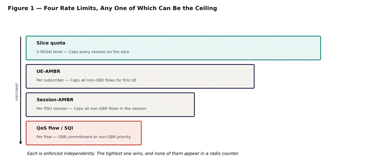
Figure 1 — four independent rate limits. Each is enforced separately; the tightest one is the ceiling.
Part 2 — The four rate limits, and which one is biting
Four separate mechanisms can cap a session’s throughput, and they operate at different scopes. Understanding which one applies to a given symptom is most of the diagnosis.
| Limit | Scope | How it presents |
| Slice quota | Every session on the S-NSSAI | Multiple unrelated customers on the same slice degrade together |
| UE-AMBR | All non-GBR flows for one UE | One device is capped regardless of how many sessions it opens |
| Session-AMBR | All non-GBR flows in one PDU session | A second session on the same UE is unaffected |
| QoS flow / 5QI | One flow within a session | One traffic type is slow while others on the same session are fine |
The test that separates them
Scope is diagnostic. If a second PDU session on the same device achieves full throughput, the constraint is session-AMBR rather than UE-AMBR. If every device on the same subscription profile shows the same ceiling, it is subscription data rather than anything session-specific. If unrelated customers sharing a slice degrade at the same times, it is slice-level.
One further property distinguishes all four from radio and transport faults: a policy ceiling applies to UDP as readily as TCP. If a UDP throughput test hits exactly the same number as a TCP test, the constraint is not loss, latency or window size. Something is enforcing a rate.
If UDP and TCP hit the identical figure, stop investigating transport. A rate limit is being enforced, and enforcement is a core function.
Part 3 — Session-AMBR and UE-AMBR
Aggregate Maximum Bit Rate is the most common policy ceiling and the easiest to overlook, because it produces a result that looks stable rather than constrained.
What each one covers
Session-AMBR caps the total of all non-GBR flows within a single PDU session. It is provided by the SMF from subscription data during session establishment and enforced at the UPF.
UE-AMBR caps the total of all non-GBR flows across every session the UE has open. It is enforced by the gNB rather than the core, which means it constrains the scheduler directly.
Neither applies to guaranteed bit rate flows. A GBR flow has its own commitment and sits outside the AMBR calculation entirely — which is occasionally the fix when an enterprise customer needs a specific application protected from a shared ceiling.
The signature
An AMBR ceiling produces a flat throughput curve. Not a degraded one, not an erratic one — flat. Radio conditions improve and throughput does not. The cell empties out at three in the morning and throughput does not change. Every test returns a number within a few percent of the same figure, often a suspiciously round one: exactly 50, exactly 100, exactly 200.
The reason this gets missed is that stability reads as health. An engineer looking at a consistent throughput graph sees a well-behaved link, not a capped one. The tell is the absence of variance, and it requires deliberately looking for it.
Triage steps
- Compare the observed figure against the subscribed session-AMBR and UE-AMBR in the subscription profile. If they match, the investigation is over.
- Open a second PDU session on the same device and test again. Full throughput on the second session means session-AMBR; the same ceiling shared across both means UE-AMBR.
- Test a different device on the same subscription. An identical ceiling confirms subscription data rather than anything device-specific.
- Check whether the AMBR value in use matches what the customer contracted for. A mismatch between the sold service and the provisioned profile is a common and entirely fixable finding.
Which values are applied and where they come from is decided during PDU session establishment — the flow is covered in Module 1 of this course, and the division of responsibility between the SMF that fetches the policy and the UPF that enforces it is covered in control and user plane separation.
Part 4 — QoS flows, 5QI and where differentiation is lost
The QoS framework in 5G is more granular than LTE’s bearer model, and that granularity introduces a failure mode that did not previously exist: differentiation configured in the core can be silently discarded at the radio.
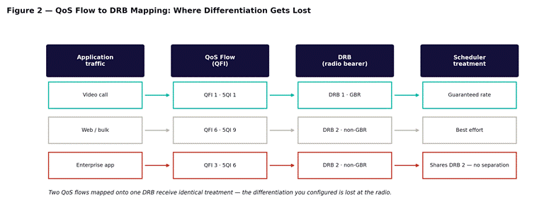
Figure 2 — two QoS flows mapped onto the same DRB receive identical scheduler treatment.
The mapping problem
Traffic is classified into QoS flows, each identified by a QFI and characterized by a 5QI that specifies priority, delay budget and error rate. Those flows are then mapped onto data radio bearers by the gNB. The mapping is the gNB’s decision, not the core’s.
If two QoS flows with different 5QI values are mapped onto the same DRB, they receive identical scheduler treatment. The differentiation exists in the core, is signaled to the RAN, and then evaporates. An enterprise application configured for priority handling competes on equal terms with bulk web traffic, and every core-side counter shows the QoS policy applied correctly.
What to check
| Check | Where | What a fault looks like |
| Which QFI the traffic mapped to | SMF or UPF trace | Traffic on the default flow instead of the configured one |
| Which 5QI that QFI carries | Subscription and PCC rules | A 5QI that does not match what was sold |
| QoS flow to DRB mapping | RRCReconfiguration message | Two differentiated flows sharing one DRB |
| ARP priority and pre-emption | PCC rules | Low ARP losing resources under congestion |
The third row is the one worth reading the actual signaling for. The RRCReconfiguration that establishes the bearers contains the mapping explicitly. Reading it is the only way to confirm what the gNB actually did rather than what the core asked for.
The standardized 5QI table and what each value commits the network to are covered in QoS and 5QI. It is worth having open while reading a PCC rule, because a 5QI value on its own means nothing without the delay budget and priority level it maps to.
Part 5 — Slice-level limits
Network slicing introduces a ceiling above everything discussed so far. A slice can have its own aggregate rate limit and its own admission control, and both apply before any per-session or per-UE limit is considered.
Two distinct slice failures
The first is admission: a session cannot be established at all because slice resources are exhausted. That produces the 5GSM causes #67 and #69 covered in Module 2, and it is a connection failure rather than a throughput one.
The second is enforcement: the session establishes normally and is then rate-limited to a share of the slice’s allocation. Nothing rejects anything. Throughput is simply lower than the per-session policy would suggest, and it varies with how many other sessions are active on the same slice. This is the throughput analogue of the admission failures in Module 3 of this course, where a session that establishes cleanly can still be released for reasons no radio counter records.
The signature
- Multiple unrelated customers degrade at the same times, because they share a slice rather than a cell.
- The degradation does not correlate with any single cell’s load — it appears across the footprint the slice covers.
- Per-session AMBR checks come back clean, because the session limit is not what is binding.
This one is genuinely hard to spot from the RAN, because the affected sessions have nothing geographically in common. Two enterprise customers in different cities degrading simultaneously is not a coincidence to be explained away; it is the signature of a shared slice.
How slices are identified, selected and provisioned with resources is covered in network slicing — one physical network, many virtual ones. The S-NSSAI negotiation that determines which slice a session lands on happens during registration, covered in Module 2 of this course.
Part 6 — The UPF itself
Every rate limit discussed so far is enforced somewhere, and for most of them that somewhere is the User Plane Function. The UPF is also a piece of software running on hardware with finite capacity, and when it runs short the symptoms look nothing like a policy problem.
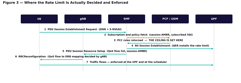
Figure 3 — the policy is fetched by the SMF, installed at the UPF as a QER, and enforced on every packet.
What a loaded UPF looks like
| Symptom | Mechanism | Distinguishing feature |
| Throughput falls at busy hour | Packet processing capacity reached | Recovers off-peak; correlates with UPF CPU |
| Latency rises with load | Queuing inside the UPF | RTT to the UPF climbs while radio latency is stable |
| Loss appears under load | Buffer exhaustion | Loss is at the UPF hop specifically, not end to end |
| Sessions fail to establish | N4 or resource exhaustion | 5GSM cause #26, insufficient resources |
The distinguishing feature throughout is scope. A loaded UPF affects every session anchored to it, regardless of which cell those sessions are on. If poor throughput correlates with a UPF rather than with a geography, that is the finding — and it is invisible from any RAN dashboard. Module 5 of this course covers the related case where the UPF is healthy but sits too far away, and massive MIMO and beamforming covers the radio-side ceiling that has to be excluded before any of this applies.
The related case worth repeating from Modules 3 and 5: if the N4 session has failed, the control plane can be entirely healthy while no traffic flows at all. Check PFCP heartbeat status before spending time on rate limits when a session appears established and carries nothing.
Which network function owns which part of this is worth being precise about, because the SMF decides and the UPF enforces — the AMF, SMF and UPF breakdown maps each responsibility, and Module 5 of this course covers the transport path between the gNB and the UPF that a distant anchoring decision lengthens.
Part 7 — Step-by-step: the 5G QoS troubleshooting procedure
Entry condition: Modules 4 and 5 have ruled out the radio and the transport path. Rank, MCS, HARQ and PRB utilization are healthy; interface speed, MTU, latency and loss are clean.
Stage 1 — Confirm a rate is being enforced
- Run a UDP throughput test and a TCP test. If both return the same figure, a rate limit is being enforced and the remainder of this module applies. If UDP substantially exceeds TCP, go back to Module 5 — that is loss or latency.
- Check whether the figure is flat across time of day and radio conditions. Variance points away from policy.
- Note whether the number is suspiciously round. Policy limits are configured by humans and look like it.
Stage 2 — Identify which limit
- Compare against the subscribed session-AMBR. Match means you are done.
- Open a second session on the same device. Full throughput on the second means session-AMBR, not UE-AMBR.
- Test a second device on the same subscription profile. Same ceiling means subscription data.
- Check whether other customers on the same slice degrade at the same times. If so, the constraint is slice-level and none of the per-session checks will reveal it.
Stage 3 — If it is not an aggregate limit, check the mapping
- Identify which QoS flow the traffic actually mapped to — not which one you expect.
- Confirm the 5QI on that flow matches the subscription and the contracted service.
- Read the QoS flow to DRB mapping in the RRCReconfiguration. Two differentiated flows on one DRB is the fault.
- Check the ARP value. Under congestion, a low ARP loses resources to higher-priority traffic by design.
Stage 4 — Check the UPF
- Correlate the degradation against UPF load rather than cell load.
- Check whether every affected session is anchored to the same UPF, regardless of geography.
- Verify PFCP session state and heartbeat if traffic is absent rather than merely slow.
Part 8 — Counters and where to look
Core-side evidence comes from the SMF, the PCF and the UPF rather than from the RAN, which is part of why this fault class is often left uninvestigated — the person holding the ticket frequently has no access to any of them.
| Where | What to collect | What it tells you |
| Subscription profile (UDM) | session-AMBR, UE-AMBR, subscribed 5QI | The contracted ceiling, and whether it matches what was sold |
| PCC rules (PCF) | Applied 5QI, ARP, rate limits | What policy was actually installed for this session |
| UPF | QER enforcement counters, CPU, throughput per session | Whether the limit is being hit, and whether the UPF is the constraint |
| RRCReconfiguration | QoS flow to DRB mapping | What the gNB did with the flows the core defined |
| Slice level | Aggregate slice throughput against its quota | Whether the constraint sits above the session entirely |
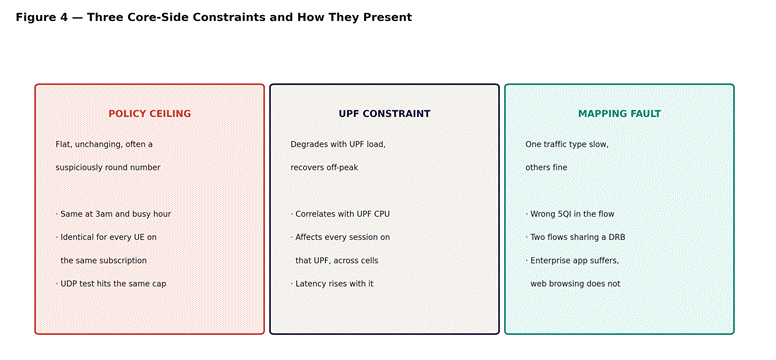
Figure 4 — the three core-side constraints and the signature that identifies each.
The subscription profile row deserves emphasis because it resolves a surprising share of enterprise throughput complaints outright. A customer sold a 500 Mbps service whose profile was provisioned at 100 is not a network fault at all — it is an order-handling error, and no amount of engineering investigation will surface it if nobody thinks to compare the two.
Part 9 — Worked example
A bank reports that its branch connectivity service delivers around 95 Mbps against a contracted 500. The complaint has been open for three weeks and has already been through radio optimization and a transport audit, both of which found nothing.
Module 4’s checks confirm the radio: SINR above 22 dB, rank 3 to 4, MCS high, HARQ at target, PRB utilization under 30 percent. Module 5’s checks confirm the transport: interfaces at the correct speed, path MTU correct, RTT to the UPF at 6 milliseconds, no measurable loss.
Stage 1 of this module gives the first real signal. A UDP test returns 95 Mbps — the identical figure to TCP. Loss and latency cannot produce that; something is enforcing a rate.
Stage 2 narrows it. A second PDU session on the same device also returns 95 Mbps, and the two together still total 95. That rules out session-AMBR and points at UE-AMBR. A second device on the same subscription profile returns the same figure, confirming subscription data rather than anything device-specific.
The subscription profile shows a UE-AMBR of 100 Mbps. The contracted service is 500. The provisioning that followed the order applied a default profile rather than the one the contract specified, and nothing downstream ever compared them.
The fix is a subscription data change, applied by the provisioning team, taking minutes. Three weeks of radio and transport investigation found nothing because there was nothing in either place to find — and the single test that would have pointed here on day one was comparing UDP against TCP.
Three weeks of engineering effort, resolved by comparing the contract against the profile. Check what was sold before investigating why it is slow.
Part 10 — The full decision tree
Step 1 — Establish that policy is the layer
- Confirm Modules 4 and 5 are clean. This module has no meaning until the radio and transport are ruled out.
- Run UDP against TCP. Identical figures mean a rate is being enforced. Divergent figures send you back to Module 5.
- Check for flatness. A policy ceiling does not vary with conditions.
Step 2 — Work the scope outward
- Per flow: is one traffic type slow while others are fine? Check 5QI and DRB mapping.
- Per session: does a second session get full throughput? Session-AMBR.
- Per UE: does a second device on the same profile hit the same ceiling? Subscription data.
- Per slice: do unrelated customers degrade together? Slice quota.
- Per UPF: are all affected sessions anchored to the same UPF regardless of geography? UPF load.
Step 3 — Compare against what was sold
Before changing anything, compare the provisioned profile against the contracted service. A mismatch is common, entirely fixable, and belongs to a different team than the one usually holding the ticket. This check costs a minute and resolves a meaningful share of enterprise cases outright.
Step 4 — Change one thing, and route it correctly
Policy changes are made by whoever owns subscription data or slice design, not by the RAN team. Identify the correct owner before proposing a fix, state precisely which parameter should change and to what, and re-measure after a full busy hour. Confirm against the customer’s original figure rather than against the counter you changed.
What comes next
That completes fault class C. The remaining modules cover the areas this course has touched but not yet worked in full: handover failure signatures in depth, and the EN-DC and SCG failure modes specific to non-standalone deployments. If you need the underlying architecture, the 14-module Introduction to 5G course covers the air interface and core design this course assumes, including the CU/DU/RU split that determines where the scheduler making the DRB mapping decision actually lives.