

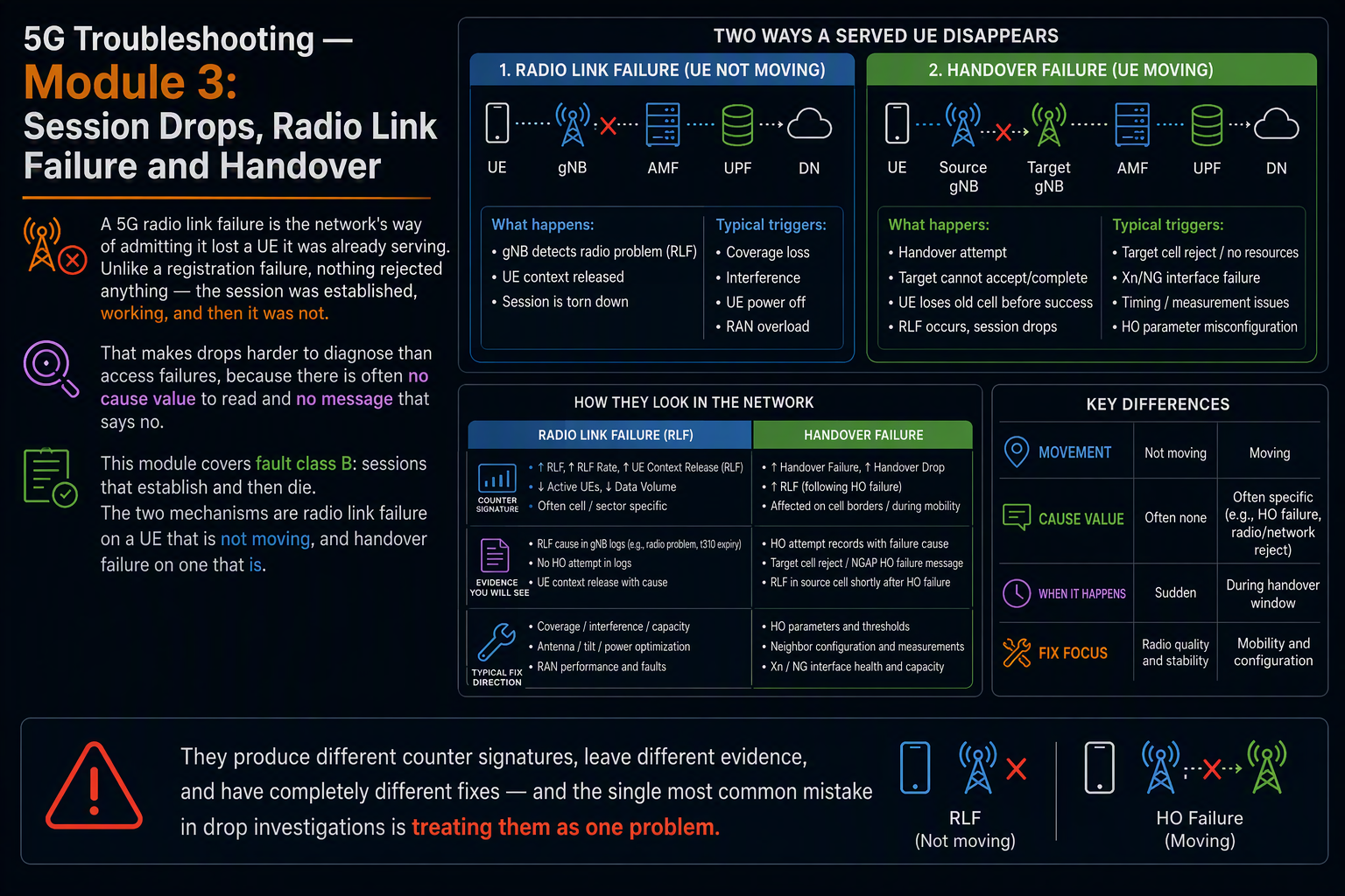
A 5G radio link failure is the network’s way of admitting it lost a UE it was already serving. Unlike a registration failure, nothing rejected anything — the session was established, working, and then it was not. That makes drops harder to diagnose than access failures, because there is often no cause value to read and no message that says no.
This module covers fault class B: sessions that establish and then die. The two mechanisms are radio link failure on a UE that is not moving, and handover failure on one that is. They produce different counter signatures, leave different evidence, and have completely different fixes — and the single most common mistake in drop investigations is treating them as one problem.
A registration failure tells you why it was refused. A drop makes you reconstruct what happened from the wreckage.
In this module
- Part 1 — Drop, or something that looks like a drop
- Part 2 — The 5G radio link failure timeline: N310, T310, N311, T311
- Part 3 — Beam failure recovery: the layer below RLF
- Part 4 — RRC re-establishment, and why some drops are invisible
- Part 5 — Reading an RLF report after a 5G radio link failure
- Part 6 — Handover failure: the three signatures
- Part 7 — Step-by-step: handover failure triage
- Part 8 — EN-DC and SCG failure
- Part 9 — Core-side and policy-side drops
- Part 10 — Counters and vendor mapping
- Part 11 — Worked example
- Part 12 — The full decision tree
Part 1 — Drop, or something that looks like a drop
Before investigating, confirm you have a drop at all. Four things get reported as drops and only two of them are:
| Reported as | Actually is | How to tell |
| Call/session dropped | A genuine RLF or handover failure | Abnormal release counter pegs; RLF report available |
| Call dropped | Normal release after inactivity | Release cause is normal; inactivity timer expired first |
| Network keeps dropping | Repeated re-establishment, session preserved | User sees a stall, not a disconnect; no abnormal release |
| 5G keeps dropping | EN-DC SCG release, LTE unaffected | Data continues; only the 5G indicator disappears |
The third and fourth rows matter most. A UE that re-establishes successfully after RLF keeps its session — the user experiences a two-second stall, not a disconnection, and no drop counter pegs. If you are chasing a complaint of “it keeps cutting out” and the drop rate looks fine, this is usually why. The failure is real and the counter is right; they are measuring different things.
Equally, in non-standalone deployments the loss of the NR leg is not a drop at all. The LTE anchor keeps the session alive and the user keeps their data, but the 5G icon disappears and they report it as a drop. That investigation belongs in Part 7 and has nothing to do with RLF on the primary cell.
Confirm you have a drop before you investigate one. Half of reported drops are re-establishments or SCG releases.
Part 2 — The 5G radio link failure timeline
Radio link failure is not an event. It is the end of a sequence of timers and counters, each of which is configurable, and understanding the sequence is what lets you tell a coverage problem from a configuration problem.
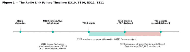
Figure 1 — the radio link failure timeline. Recovery is possible for the whole duration of T310; only its expiry declares RLF.
The sequence
The physical layer continuously assesses the downlink radio link quality against two thresholds. When it falls below the out-of-sync threshold, the layer reports an out-of-sync indication to RRC. When N310 consecutive out-of-sync indications arrive, RRC starts T310.
While T310 runs, the UE is still connected and still trying. If the physical layer delivers N311 consecutive in-sync indications before T310 expires, the timer stops and the UE recovers with no failure recorded anywhere. This is the invisible case — the link degraded badly enough to start the failure process and then recovered, and unless you are looking at physical-layer statistics you will never know it happened.
If T310 expires, radio link failure is declared. The UE releases the connection, starts T311, and searches for a suitable cell to re-establish on. If it finds one and re-establishment succeeds, the session survives. If T311 expires first, the UE goes to RRC_IDLE and the session is genuinely gone.
| Parameter | Typical setting | What tuning it actually does |
| N310 | 1 to 20 | How many bad reports before the clock starts. Low = twitchy, high = slow to react |
| T310 | 500 ms to 2 s | The recovery window. Longer = more recoveries, but longer stalls when it fails anyway |
| N311 | 1 to 10 | How much good news is needed to cancel. Low = optimistic recovery |
| T311 | 1 s to 30 s | How long the UE hunts for a cell before giving up entirely |
The tuning trade-off is real and there is no universally correct answer. A long T310 recovers more sessions but produces longer user-visible stalls in the cases that fail anyway. A short T310 declares failure quickly and lets re-establishment start sooner, which can be better when a good neighbor cell is available and worse when it is not. If drops are concentrated in an area with poor neighbor coverage, shortening T310 makes things worse, not better.
These are the same mechanics used in LTE and the parameter names are identical, so if the interaction between the counters and timers is unfamiliar, radio link failure in LTE covers the underlying logic in more detail and it transfers directly to NR.
Part 3 — Beam failure recovery: the layer below RLF
NR adds a recovery mechanism that has no equivalent in LTE, and missing it leads to a lot of wasted RLF investigation. On a beamformed cell the UE is served by a specific beam, and that beam can fail while the cell remains perfectly good. Beam failure recovery handles this without ever involving the RLF timers.
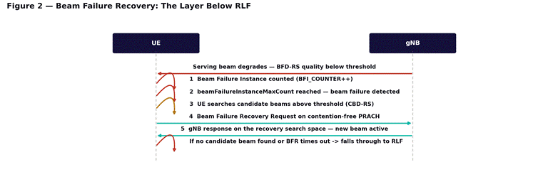
Figure 2 — beam failure recovery. This runs entirely below the RLF layer and only falls through to T310 if it fails.
The UE monitors reference signals associated with its serving beam. Each time quality falls below threshold, a beam failure instance is counted. When the count reaches beamFailureInstanceMaxCount, beam failure is declared and the UE searches its configured candidate beams for one above the recovery threshold. If it finds one, it sends a recovery request on a dedicated contention-free PRACH resource and the gNB switches it to the new beam.
The whole exchange takes tens of milliseconds and produces no RLF, no drop, and nothing in any drop counter. What it does produce is a brief throughput stall — which is why a UE can report repeated cutting out while your drop rate and RLF counts both look healthy.
When beam failure matters for a drop investigation
- Frequent beam failure recovery with no RLF: the user perceives stalls; the network sees nothing wrong. This is the invisible complaint.
- Beam failure recovery attempts that fail: no candidate beam is above threshold, and the UE falls through to the RLF path. The root cause is beam coverage, not cell coverage.
- Recovery request failures on PRACH: the candidate beam was found but could not be accessed — an uplink problem, not a beam problem.
The practical signature is a cell where beam failure recovery attempts are high but RLF is normal. That is a beam-level coverage hole inside an apparently well-covered cell, and it is usually caused by beam set configuration rather than by anything in the link budget. Sites with obstructions in one azimuth are the usual candidates.
This is a mechanism specific to beamformed deployments, so it interacts directly with how the beam set is planned — massive MIMO and beamforming covers how SSB beams and CSI-RS beams are constructed and why the candidate set matters here.
Part 4 — RRC re-establishment, and why some drops are invisible
After RLF the UE does not give up. It selects a cell and attempts re-establishment, and whether that succeeds determines whether anyone ever sees a drop.
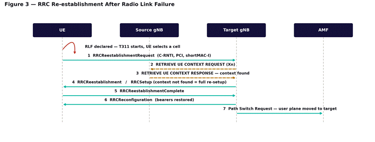
Figure 3 — RRC re-establishment. Whether the target can retrieve the UE context decides between a stall and a dropped session.
The decision point is step 2
The UE presents its old C-RNTI, the PCI of the cell it failed on, and a short MAC-I that authenticates the request. The target gNB uses these to find which node held the context and retrieves it over Xn. If it succeeds, the UE is restored with its bearers intact and the user sees a brief stall.
If the target cannot retrieve the context — no Xn relation to the source, the source has already discarded the context, or the shortMAC-I does not validate — it responds with RRCSetup instead of RRCReestablishment. That is a fallback to a completely fresh connection: the session is gone, the UE must register again, and the user sees a real disconnection.
What this means for triage
- A high RLF count with a high re-establishment success rate is a coverage problem with a working mobility configuration. Users complain about stalls.
- A high RLF count with a low re-establishment success rate is a coverage problem plus a mobility configuration problem. Users complain about drops.
- A low RLF count with user complaints about drops means you are looking at the wrong layer — go to Part 9.
Re-establishment failure is very often an Xn problem rather than a radio problem. If UEs are failing over to RRCSetup rather than being restored, check whether the cells they land on have Xn relations with the cells they failed on. Missing Xn between two neighboring gNBs turns every recoverable RLF in that area into a dropped session.
Part 5 — Reading an RLF report after a 5G radio link failure
When a UE recovers after a 5G radio link failure it can carry a report of what happened and hand it to the network on request. This is the closest thing to a black box recorder in mobile networks, and it is chronically underused.
| Field | What it tells you |
| Measurement results | RSRP and RSRQ of the failed cell and its neighbors at the moment of failure |
| Failure type | RLF, or handover failure — these are distinguished explicitly |
| Previous PCI and cell ID | Which cell the UE was on, and where it came from |
| Reconnect cell ID | Where it recovered, which tells you what coverage was actually available |
| Time since failure | How long the UE spent recovering |
| Connection failure type | For handover failures: whether it was too-late, too-early or wrong-cell |
The measurement results field is the one that settles arguments. If the serving cell was at -118 dBm and the best neighbor was at -95 dBm at the moment of failure, this was a mobility problem — a handover should have happened and did not. If the serving cell was at -118 dBm and every neighbor was worse, it was a coverage problem and no parameter change will fix it. Those two conclusions lead to entirely different work, and without the report you are guessing between them.
To use RLF reports the network must request them. The gNB includes a flag in the UEInformationRequest after a UE reconnects, and the UE responds with the stored report. This is a feature that has to be enabled, and in many networks it simply is not — which means the single most useful piece of drop evidence is being discarded by default. Confirm it is switched on before you accept that a drop investigation is impossible.
The RLF report tells you whether a handover should have happened. Without it, coverage and mobility problems look identical.
Part 6 — Handover failure: the three signatures
Handover failures are the other half of fault class B, and unlike RLF on a stationary UE they are almost always fixable through configuration. Three signatures cover nearly all of them.
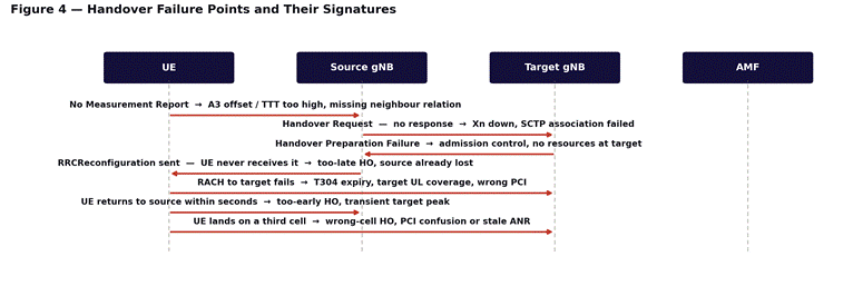
Figure 4 — the handover procedure annotated with where it fails and what each failure means.
Too-late handover
The UE experiences RLF on the source cell before the handover completes, then re-establishes on a different cell. The decision to hand over came too late — by the time the measurement report was acted upon, the source was already unusable.
Causes: the A3 offset is too high, time-to-trigger is too long, the measurement report was lost, or the UE is moving faster than the parameters assume. This is the dominant failure mode on highways and any high-mobility route, and it produces drops rather than stalls because the source is gone before recovery can start.
Too-early handover
The handover succeeds, and within seconds the UE experiences RLF on the target and re-establishes back on the source. The network handed over to a cell that was momentarily strong — a reflection, a brief line of sight — and was not actually a viable serving cell.
Causes: the A3 offset is too low, time-to-trigger is too short, or the neighbor is a small cell with a coverage island. The fix is almost always to increase time-to-trigger so transient peaks do not trigger decisions.
Wrong-cell handover
The UE hands over, fails, and re-establishes on a cell that is neither the source nor the intended target. The network picked a target that was not the right one.
Causes: PCI confusion — two cells sharing a PCI within measurable range, so the UE reports one and the network prepares the other — or a stale neighbor relation created by ANR under conditions that no longer apply. This one is worth taking seriously because PCI confusion also corrupts other measurements and will produce unexplained failures elsewhere.
| Signature | What the UE did | Usual fix |
| Too late | RLF on source, recovered elsewhere | Lower A3 offset, shorten time-to-trigger |
| Too early | Handover succeeded, returned to source | Raise time-to-trigger, review small-cell thresholds |
| Wrong cell | Landed on an unintended third cell | Resolve PCI confusion, audit neighbor relations |
Conditional handover changes this picture substantially, because the UE is given the target configuration in advance and executes autonomously when a condition is met — which removes the window where a measurement report can be lost. Conditional handover in 5G NR covers how it works, and mobility and handover — Xn, N2 and session continuity covers the baseline procedure these failures interrupt.
Part 7 — Step-by-step: handover failure triage
- Confirm the failure is mobility-related. Check whether drops correlate with cell edges and with UE speed. Stationary UEs dropping in cell centers are not a handover problem.
- Split handover failures by neighbor pair, not by cell. A cell with a 2 percent failure rate may have one neighbor pair failing at 40 percent and nine performing perfectly.
- Pull the RLF reports and read the connection failure type field. Too-late, too-early and wrong-cell are distinguished explicitly — do not infer what the report will tell you.
- For too-late failures, check the A3 offset and time-to-trigger against the actual UE speed on that route. Parameters tuned for pedestrian movement fail on a highway.
- For too-early failures, check whether the target is a small cell or has an irregular footprint. Raising time-to-trigger is the first lever.
- For wrong-cell failures, audit PCIs within measurement range. Two cells with the same PCI visible from one location is a planning error that needs fixing regardless of its effect on handover.
- Check the Xn relation exists and is healthy for every failing pair. A missing Xn forces N2-based handover, which is slower and fails more often at speed.
- Verify the neighbor relation is bidirectional. ANR sometimes creates one-way relations, and handovers work in one direction and fail in the other.
Part 8 — EN-DC and SCG failure
In non-standalone deployments the NR leg can fail without the session dropping. The LTE anchor holds the connection, the user keeps their data at LTE speed, and the only visible symptom is the 5G indicator disappearing. Users report this as a drop; it is not one.
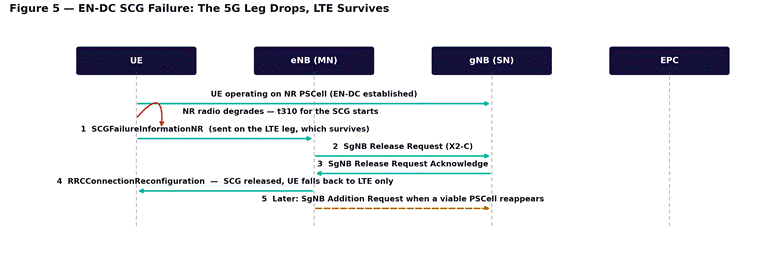
Figure 5 — SCG failure in EN-DC. The failure is reported over the surviving LTE leg, which is why nothing disconnects.
The key structural point is in step 1. The UE reports the NR failure over the LTE connection, which is still working. That is what makes SCG failure recoverable and undramatic — but it also means the failure never appears in any counter that measures dropped sessions. If you are looking for NR problems in drop statistics on an NSA network, you will not find them.
The three SCG failure types
| Failure type | Mechanism | Points at |
| t310 expiry | NR downlink degraded past recovery | NR coverage — the PSCell was too weak |
| Random access problem | UE could not access the PSCell | NR uplink — classic downlink/uplink imbalance |
| Max RLC retransmissions | Too many failed retransmissions | Interference, or badly mismatched link adaptation |
The random access problem case deserves attention because it is the most common and the most misdiagnosed. The B1 threshold that triggers SgNB addition is based on downlink measurement, but staying on the PSCell requires a working uplink. Mid-band NR with massive MIMO produces a downlink that reaches considerably further than the uplink can answer, so a UE can measure an excellent NR cell it cannot actually use. Raising the B1 threshold shrinks the 5G footprint slightly and eliminates most of these failures. The access procedure itself is covered in NR initial access — cell search, SSB and random access, and the preamble side in RACH preamble planning.
A high SCG failure rate with low LTE drop rate is the healthy-looking version of a real problem: nothing is dropping, but users are spending far less time on 5G than your coverage maps suggest. Track SCG addition success and SCG retention separately from drop rate, or this stays invisible.
Part 9 — Core-side and policy-side drops
Not every drop is radio. If RLF counts are normal and handover performance is healthy but sessions still end, work upward.
| Mechanism | Symptom | Where to look |
| Inactivity release | Sessions end after quiet periods | RRC inactivity timer; normal, not a fault |
| AMF-initiated release | Sessions end network-wide, no radio signature | AMF logs, mobility management timers |
| PDU session release by SMF | Data stops, RRC connection survives | SMF logs, session-AMBR, policy changes |
| N4 path failure | Traffic stops without any signaling event | PFCP heartbeat between SMF and UPF |
| Periodic registration failure | UE drops out after long idle periods | T3512, and the Module 2 registration procedure |
The N4 path failure case is worth knowing because it produces the most confusing symptom in the whole fault class: the UE remains connected, the radio is fine, RRC is up, and no traffic flows. Nothing in the RAN indicates a problem because from the RAN’s perspective there is none. If a session appears alive but carries nothing, check PFCP heartbeats before spending a day on the radio.
The division of labor here is why understanding control and user plane separation matters for drop investigations specifically — the control plane can be perfectly healthy while the user plane is dead. The AMF, SMF and UPF breakdown identifies which element releases what, and QoS and 5QI covers the policy layer that can terminate a flow without terminating the session.
Part 10 — Counters and vendor mapping
Drop investigations depend on a small number of counters, and the most important thing about them is which pair you compare. A drop rate on its own tells you almost nothing; a drop rate against RLF count against re-establishment success tells you where the failure sits.
The counters that matter
| 3GPP TS 28.552 reference | Measures | Read it against |
| DRB.RelActNbr / .RelNbr | Abnormal vs total bearer releases | Total sessions — gives the true drop rate |
| RRC.ConnReEstabAtt / .Succ | Re-establishment attempts and successes | RLF count — low success turns stalls into drops |
| MR.HO.ExeAtt / .ExeSucc | Handover execution | Split by neighbor pair, never cell-aggregate |
| MR.HO.PrepAtt / .PrepFail | Handover preparation | Isolates target admission control from radio failure |
| RRC.ConnEstabFail.T300Expiry | UE gave up during setup | Distinguishes coverage from rejection |
Vendor equivalents
| Measurement point | Huawei (MAE-Access) | Ericsson (ENM) |
| RRC re-establishment | N.RRC.ReEst.Att / .Succ style naming | pm-prefixed RRC re-establishment counters |
| Handover execution | N.NgHo / N.XnHo domain counters | pm-prefixed handover execution counters |
| Abnormal release | N.DRB.Abnorm.Rel domain | pm-prefixed abnormal release counters |
The same caution applies as in Module 2: Huawei’s N.<Domain>.<Metric> convention and Ericsson’s pm prefix are reliable, but confirm the exact strings against the PM counter reference for your own software baseline before building a report on them. The measurement points are defined by the protocol and are identical across vendors; only the labels differ. For Nokia, the equivalents sit in numbered NetAct measurement classes rather than descriptive names.
The three comparisons that isolate a drop
- Drop rate against RLF count. Drops without RLF means the cause is not radio — go to Part 9.
- RLF count against re-establishment success. High RLF with high recovery is a coverage problem users experience as stalls; high RLF with low recovery is a coverage problem plus a mobility or Xn problem, and users experience it as drops.
- Handover preparation failure against handover execution failure. Preparation failures are the target refusing; execution failures are the UE not arriving. Different teams, different fixes.
Never read a drop rate on its own. It is the comparison between counters that tells you where the session died.
Part 11 — Worked example
A cluster of three sites along a highway shows a drop rate of 3.1 percent against a network average of 0.4. Coverage looks adequate on the prediction maps, RSRP samples from drive test are mostly better than -105 dBm, and two rounds of tilt optimization have not moved the number.
Working the method. Step 1: the abnormal release counter has genuinely moved, so these are real drops rather than re-establishments. Step 2: RLF counts are high and re-establishment success is around 40 percent against a network average above 85. That second figure is the anomaly — the drops are not being caused by the radio alone, because most RLF events elsewhere on the network recover.
Step 3: drops correlate strongly with speed. Stationary UEs in the same cells are fine. That points at mobility rather than coverage, which is consistent with two rounds of tilt work achieving nothing.
Step 4: the RLF reports settle it. The connection failure type field reads too-late handover on most of them, and the measurement results show a neighbor cell 12 dB stronger than the serving cell at the moment of failure. A handover should have happened well before the link failed.
The mechanism is time-to-trigger set for pedestrian mobility on a route where UEs are moving at 120 km/h. By the time the condition has been satisfied for the configured duration, the UE has travelled far enough that the source cell is no longer viable. The 40 percent re-establishment success is a second, separate problem: the cells the UEs land on have no Xn relations with the cells they failed on, so context retrieval fails and every recoverable failure becomes a dropped session.
Two fixes, applied one at a time. Shortening time-to-trigger on the highway cells addresses the handover timing. Adding the missing Xn relations converts the remaining failures from drops into stalls. Neither would have been found by more tilt optimization, and neither was visible in the drop rate alone — it took the comparison between RLF count and re-establishment success to point at the second problem at all.
Part 12 — The full decision tree
Step 1 — Confirm it is a drop
- Check whether the abnormal release counter actually moved. If it did not, you may be looking at re-establishments or SCG releases rather than drops.
- In NSA, check whether LTE data continued. If it did, this is SCG failure — go to Part 8.
- Check the release cause. A normal release after inactivity is not a fault.
Step 2 — Radio or not
- Compare RLF counts against the drop count. RLF near zero with drops occurring means the cause is not radio — go to Part 9.
- Check re-establishment success rate. Low success turns recoverable failures into drops and is often an Xn problem, not a coverage one.
Step 3 — Stationary or moving
- Correlate drops with speed and with position. Cell-edge drops on moving UEs are handover failures; cell-center drops on stationary UEs are coverage or interference.
- For moving UEs, go to Part 6 and identify which of the three signatures applies before changing any parameter.
Step 4 — Read the evidence before tuning
- Pull RLF reports. If the feature is not enabled, enable it and wait rather than guessing — a week of real reports beats a month of parameter changes.
- Check the measurement results field: was there a better neighbor at the moment of failure? That single field separates mobility problems from coverage problems.
Step 5 — One change, then measure
- Change one mobility parameter at a time. A3 offset and time-to-trigger interact, and changing both leaves you unable to attribute the result.
- Allow at least a full day before judging. Drop rates are heavily influenced by traffic patterns and a single busy hour proves nothing.
- Confirm against the original complaint, not the counter. A drop rate that improves while users still report cutting out means you moved failures from one category into another.
What comes next
Module 4 takes fault class C — connected but slow — starting with the radio side: rank collapse, MCS behavior, HARQ retransmission and PRB utilization, and how to tell a link problem from a scheduling problem. Modules 5 and 6 continue into transport and core causes of low throughput. If you need the underlying architecture, the 14-module Introduction to 5G course covers the air interface and core design this course assumes, including massive MIMO and beamforming, which Module 4 builds on directly.